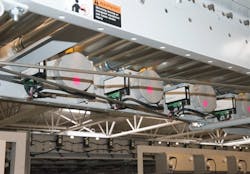
While some may claim that direct-current (DC) motors are no longer relevant, that is definitely not the case. DC motors and DC converters/drives are alive and well in industry, driven by many applications in which they are the best option (see Image 1). Alternating-current (AC) motors have certainly decreased DC motor sales, and they do confer advantages in some applications. Understanding the differences between AC and DC motors reveals where each works best and helps guide selection and specification.
DC motor designs
Popular DC motor designs include:
- Permanent magnet
- Brushless
- Shunt
- Series
- Compound wound or stabilized shunt
The basic operation of all these designs is similar. A current-carrying conductor is placed in a magnetic field, and applying power through these conductors causes motor rotation. The difference among the designs is how the electromagnetic fields are generated and where – in either the rotor or stator.
In a permanent-magnet motor, the stator is stationary and mounted to the motor frame (see Image 2). It holds permanent magnets mounted in proximity to the spinning current-carrying conductors in the rotor. Applying a voltage through brushes contacting the armature on the rotor induces the current needed to produce mechanical force, which is rotation. Connecting two wires to the motor and supplying the proper DC voltage will cause the motor to run.
Shunt, series, and compound-wound or stabilized-shunt motor designs have a rotor with electrical connections through a brush and commutator arrangement. The brush/commutator acts as a switch to apply voltage to different coil segments of the rotor as it spins.
This configuration is different in AC induction and DC brushless motors. In these motor types, the magnetic field is generated in the fixed stator. Instead of the current-carrying coils being integrated into the spinning rotor, the coils are located in the fixed stator. Instead of the permanent magnets mounted to the stationary stator, as in a DC motor, the magnets are mounted in the rotor.
This design eliminates the need to provide electrical connections through brushes in both AC induction motors and DC brushless motors because the magnetic field is rotated instead of the current-carrying conductors. The rotor with the permanent magnets is forced to move by the current and related magnetic field generated by the AC voltage fed to the stator windings.
Brushing up on DC motors
AC motors and DC brushless motors are popular and dominate many applications formerly occupied by standard DC motors. Although many reasons explain this change, one of the most notable is that AC motors require less maintenance.
All motors require at least some minimal maintenance such as keeping the fan and motor clean or greasing non-sealed bearings. However, DC motors also require monitored and scheduled replacement of the internal brushes. This is simple to perform on small motors. However, on higher horsepower (hp) DC motors, brush installation procedures are more complex and must be carefully followed.
On smaller, permanent-magnet DC motors, brushes easily and quickly can be changed. They are inexpensive and only take minutes to replace. A good rule of thumb is to replace the brushes once they reach one-third of their original length or every 2,500 hours of use, whichever comes first. This will ensure the brushes are always within specification.
Although brush maintenance is often seen as a disadvantage compared to AC motors, brushes in DC motors continue to improve. Designs that reduce brush wear, such as smaller diameter commutators, extend motor operating time between brush replacements. The design of the brush – including the surface area, shape and contact pressure – can also extend brush change intervals.
Why DC?
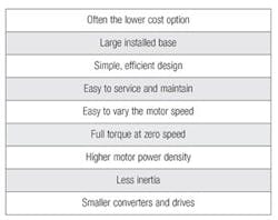
DC motors are often selected instead of AC motors for many reasons (see Table 1). DC motors and controllers are often the low-cost option when compared to inverter-duty AC motors and drives. This is especially true for fractional hp applications.
DC motors have been around for more than 140 years, so they have a large installed base and corresponding widespread familiarity with their operation and maintenance. For existing installations, replacing a DC motor with a new one – as opposed to redesigning the motor circuit to use an AC motor and drive – is almost always less expensive, quicker and easier.
Along the same lines, the simple design of DC motors makes service, maintenance and control well understood and easily supportable. Field excitation is not required, and brush replacement and motor service are well understood by the typical industrial electrician. Even speed control is simple: Just adjust the terminal voltage, often using a local potentiometer.
Additionally, until the late 1980s, when the variable frequency drive (VFD) was fully developed, DC motors were the best choice for variable speed control, and this remains a well-supported option.
Torque at low speed
While the ease of controlling motor speed was a big part of its early success, several other DC motor characteristics make them the best choice in certain applications. DC motors develop full torque at low speed and across the full operating range from zero to base speed (see Figure 1).
This makes DC motors a good choice for driving constant-torque loads – such as conveyor belts, elevators, cranes, ski lifts, extruders and mixers. These applications are often stopped when fully loaded, and the full torque of the DC motor at zero speed gets them moving again without the need for oversizing.
DC motors have a higher power density and are, therefore, smaller than an equivalent AC motor. They have no field coil in the stator, so the field coil space is saved, reducing the overall motor size. This becomes a substantial benefit in some space-constrained applications.
Smaller form factors also mean DC motors have less inertia than AC motors, offering quicker acceleration and deceleration times. This can result in a quicker cycle time on production machines that start and stop often.
Although not often needed, DC motors can be manufactured to motor power ranges of more than 4,000 hp, whereas standard low-voltage induction motors do not go above 800 to 1,200 hp. Above that, higher voltages are needed, which can greatly complicate installation and maintenance.
Modern AC motors and drives have narrowed the performance gap with their DC counterparts, but general-purpose DC motors still outperform general-purpose AC motors by many measures. To obtain comparable low-speed performance from an AC motor, much more expensive AC-inverter duty motors and VFDs must be used.
Motor control
Less electronics and rectification are required to build a DC-converter drive when compared to building an AC-inverter drive. With an AC drive, the incoming AC power must be rectified to create DC that is then converted back to AC to power the motor. DC drives need only to rectify AC power before passing it to the DC motor. DC motors can be directly fed from different power sources, even batteries.
Depending on the type of DC drive, the quality of the output power varies dramatically and is typically measured by how much ripple current is produced by the drive. The ripple current is designated by a drive’s form factor, which is the relationship of the ripple current caused by rectification relative to a pure DC current. High ripple current results in increased motor heating and possibly premature brush failure. Limiting the form factor to 1.40 or less in continuous-operation applications is good practice.
A battery is an ideal current source because its form factor is 1.0 (see Table 2), which provides constant voltage and current to power a DC motor. A pulse-width-modulated DC drive emulates pure DC closely with a form factor of 1.05, meaning only a 5 percent ripple.
A single-phase, full-wave rectified DC drive is the most common form of DC drive used in the 0.33- to 2-hp range. This drive takes an AC voltage and passes the positive half of the waveform and rectifies the negative part of the waveform to produce a waveform with a form factor of 1.4, or a 40 percent current ripple. These drives are commonly referred to as silicon-controlled rectifier (SCR) drives. Many motors are “SCR-rated,” meaning their full-load torque and power are produced even when using an SCR drive, as opposed to a more pure power source.
A simple, single-phase, half-wave rectified DC drive has a much worse form factor. These drives only pass the positive half of the AC sine wave and have a form factor of 1.9. These half-wave DC drives are not recommended for use with most DC motors.
Applications
DC motors are suitable for many applications – including conveyors, turntables and others for which adjustable speed and constant or low-speed torque are required. They also work well in dynamic braking and reversing applications, which are common in many industrial machines.
Their quick acceleration, stopping and reversing – along with their linear-speed torque curve – make the DC motor a popular choice in many new designs, particularly for fractional hp applications.
Joe Kimbrell has been a product manager for Drives, Motors & Motion Control at AutomationDirect since 2004. He graduated with a Bachelor of Science in electrical engineering (BSEE) from Georgia Tech in 1993. He started his career with Rovema Packaging Machines as the electrical engineering manager and worked there for seven years. He then moved on to Automation Intelligence, a multi-axis motion controller developer/manufacturer and system integrator for the next five years where he was the system integration engineering manager prior to joining AutomationDirect. He may be reached at [email protected].


