Common issues in batch powder dosing and how to fix them
Dosing powder is often at the core of solids processing, and any deviation can lead to losses. The final product can be off-specification if an ingredient was dosed improperly, leading to rework or even product destruction. A dosing that is not properly mastered can also hamper the productivity of the line; for example, operators will tend to dose slowly to stay within tolerances, which prevents the line to work at its nominal speed and turns it into a bottleneck for downstream processes like mixing or dissolving.
This article discusses common issues that can affect powder dosing systems — gain in weight (GIW) or loss in weight (LIW) — and proposes remedies, either by changing the design or by operating the line differently. It focuses on batch dosing and covers typical feeders: screw conveyors, vibrating tubes and valves.
Batch powder dosing process
Batch dosing of powders can be performed in two different setups:
- Gain-in-weight dosing: The dosing is driven by the equipment receiving the powder and which must be on load cells. Several feeders can be connected to the same hopper, but only one weighing can be performed at a time.
- Loss-in-weight dosing: The dosing is controlled by the equipment that is dosing the powder. Several hoppers on load cells can be connected to receiving equipment, and all ingredients can be dosed simultaneously.
These processes are discontinuous since the operations are performed one after the other. Such discontinuous process is called batch dosing. It should be noted that LIW feeders can also be operated in
continuous dosing to deliver a constant mass flow for a continuous downstream process, if they are equipped with a specific control system.
Different types of feeder units may be used depending on the product, the space available, the dosing tolerances and throughput. The most common equipment is screw conveyors, vibrating tubes or rotary valves, while some manufacturers propose vibrating valves as well. The equipment performing the weighing must be connected to the rest of the installation by flexible connections that do not transmit any forces that would falsify the weight reading. Simple, flexible connections can be used for large systems. For more sensitive systems, special designs (bellows) are preferable.
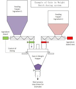
The simpler configuration as shown in Figures 1 and 2 is to dose the powder by gravity fall directly to a hopper, but other ways could be adopted
(dosing then pneumatic transport, for example). To easily explain the concept of batch powder dosing, this article focuses on the standard configuration.
Figure 1. An example of a gain-in-weight batch dosing system (All graphics courtesy of Thomas Lamotte)
Figure 2. An example of a loss-in-weight batch dosing system
Design
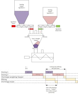
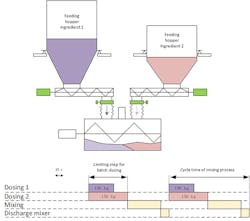
The important sizing criteria for a batch dosing system is to ensure a cycle time quick enough for a defined quantity of product dosed, the combination of both defining the throughput of the installation. When operating in a GIW system, the components must be dosed one by one; therefore, the total dosing time will be the sum of all dosing steps, including stabilization time between each dosing. With the LIW setup, all ingredients can be dosed in parallel; therefore, the total dosing time will equal the longest dosing step. Examples for a batch dry-mixing line are shown in Figures 3 and 4.
Figure 3. Gain-in-weight cycle time
Figure 4. Loss-in-weight cycle time
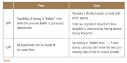
Both examples show the benefits and downsides of each way of dosing, which are explained in Table 1.
The cycle time is dependent on the dosing times of the individual ingredients. If the subsequent process operations are short (quick mixing, for example), dosing will be the limiting step and its optimization will be essential to meet the process requirements. The plant operator may attempt to dose the ingredients as quickly as possible. But this can come at the expense of the dosing accuracy. During design, a balance must be achieved in dosing speed, cost of the dosing system (type of feeder, size of the feeder, etc.) and dosing within narrow tolerances. Generally, the dosing system must be slightly faster than the batch dosing downstream to avoid a bottleneck, but without too large of a margin to stay cost-effective.
Automation
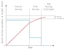
In batch processes, dosing of powder is often performed in a minimum of two steps: a fast (coarse) dosing to gain time by feeding the powder as quickly as possible, and a slow (fine) dosing to achieve the required dosing accuracy. The feeder is then stopped slightly before the setpoint to account for powder that will still flow out while the feeder stops. This last quantity is called the "inflight."
To control the dosing, the automation software relies on a set of parameters that define when to switch from one dosing speed to another (see Figure 5). A typical set of dosing parameters includes:
- Coarse dosing speed
- Remaining weight to switch to fine dosing
- Fine dosing speed
- Amount of inflight
Figure 5. Dosing automation
Troubleshooting
As previously presented, the objective of a batch powder dosing system is to deliver a defined quantity of material within defined tolerances and within a defined time. In practice, a dosing system can be a source of trouble for plant operators if it is not adjusted properly or is used to operate outside its original design. Common causes of disturbances of a bulk solids dosing system are discussed next.
Inaccurate load cells reading
To get a proper dosing, the load cells reading must be reliable. It must be understood by factory teams that load cells will almost always show a reading, however erroneous. If the reading is trusted without validation, large mistakes, which can only be noticed very late (often when the product is already packed), can happen and lead to losses or even product recall.
Operators should, therefore, be proactive in conducting a regular calibration of the load cells and making sure that the load cells are properly insulated from any perturbations. These checks will allow detection of faults early and an opportunity to correct them before they lead to large consequences.
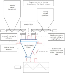
External disturbances that can affect the reading of load cells have different origins. Main causes are listed below, from most probable to least probable. Such lists can easily be turned into a troubleshooting checklist for operation or commissioning staff:
- Improper mounting of flexible connections
(bellows) - Mounting of utilities connections with tension (electrical cables, compressed air cables, etc.)
- External vibration during dosing (especially for precision dosing)
- Air draft during dosing (especially for precision dosing)
- Bad mounting (hopper in contact with static
element like cable tray or platform) - Electronic signal disturbance
- Malfunction of the load cells (out of calibration)
Powder dosing involves the displacement of product and air. The hopper supplying the product must admit air, the hopper receiving the product has to release air. Air cannot always be balanced naturally from one hopper to another since the powder dosed acts as a plug, thus filters are installed at each hopper to ensure venting.
If the breathing is hindered in some way, the pressure in the hoppers will slightly change. In effect, forces are exerted on the hoppers and their connections. These forces will overlay the readings of the load cells and will falsify the dosing. However, compensating systems have been developed to limit these effects.
On-site observation is key to identifying air balancing issues; for example, observing flexible connection inflation or collapsing will give precious indications.
Figure 6. Common sources of dosing disturbances
Excessive powder flow
One phenomenon that can lead to astonishing observations is the potential change in loose bulk density and flowability that can happen to a powder. After pneumatic transport and reception in a bin, some powders can become aerated. During dosing, the solids movement can allow the air to escape the powder. If the powder was very aerated, then an apparent fluidization can happen at the base of the hopper and significantly increase the flow of powder through the dosing equipment, which results in uncontrolled dosing. This is a clear issue since the dosing cannot be predictable, leading to erratic dosing results. Moreover, because the degree of aeration depends on the time the powder has been in the upstream hopper, this effect can occur while the plant is in full production, but not at startup or at slow inspector rates.
It is necessary to work on the root cause and design or operate the supply of material differently — for example, more time in between refill of powder and dosing or vibration to allow compaction of the powder — or apply some changes in the design of the dosing tool — for example, smaller clearances, different screw pitch, different type of augers, etc.
Managing product changes
Knowing the properties of the powder is of primary importance to ensure that the dosing will be correct. A production line, especially in the bulk solids field, will not always process the same product during its operating life. To keep innovating, companies need to introduce new materials and process them through
existing installations, which may have not been designed to handle particularities of new products.
The first element to check is the dosing sequence and the parameters that control the coarse and fine dosing. It must be noted that these parameters can change from one product to another, depending on the flow characteristics and the bulk density of the product, which means that a dosing system can suddenly appear to not perform properly when a denser or more flowable product is introduced.
It may be necessary to review the automation dosing parameters:
- Stop the feeder earlier in coarse dosing and leave more time in fine dosing.
- Slow down the feeder in fine dosing.
- Adjust inflight.
- Apply some stabilization time in between each phase to have time to stabilize the load cells reading.
- Apply a combination of the above.
If a new material presents strong flowability differences compared to the material on which the design has been based, flow problems can happen. Typically, a bad flowability can cause bridging of the powder in a hopper causing abnormally long dosing time or discharge time, which can reduce the capacity of the installation with strong economic consequences. Such radical changes may require process changes and investments in order to meet the production needs:
- Change of dosing equipment
- Change of the hoppers’ cone angles or outlet diameters
- Addition of discharging aids (vibrating bottom, fluidizing pads, mechanical agitators)
Summary
Common root causes of bad dosing discussed in this article and the potential corrective actions are summarized in Table 2.
Thomas Lamotte has 10 years of experience in process design and operation including more than six in dry-mixing and bulk solids handling. Currently a process engineer at Nestle Research Singapore, he holds two master’s degrees in process engineering from ENSIC Nancy and IFP School, France. Lamotte may be reached at [email protected].
