According to some estimates, the heat exchanger market will be worth $19.1 billion by 2021, and that growth will mainly come from the Asia-Pacific region and the chemical sector.1 In the chemical, food and plastics manufacturing industries, heat exchangers are used to heat and cool – commonly with heat transfer fluids (HTF) – base, intermediate and final products. They are also used to heat and cool air in HVAC systems.
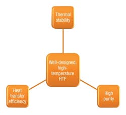
The composition of high-temperature fluids can be organic (for example, BP Transcal N, Shell Thermia B and Globatherm M) or synthetic (for example, Dowtherm A, Therminol VP-1 and Globatherm Omnitech). The organic versus synthetic decision is driven by the heat exchanger’s design features, including factors relating to life length (such as thermal stability, heat transfer efficiency and purity2) and cost (see Figure 1).
Figure 1 highlights the first important point regarding maintenance – to use a fluid with the lowest impurity levels. This will not be cost advantageous, but in biphenyl-diphenyl-based HTFs used in the solar sector, HTFs with a chlorine concentration of 0.1 percent (99.9 percent purity) have been shown to degrade slower over their lifetimes than a relatively less pure equivalent (99.5 percent purity/0.5 percent chlorine).3
In the chemical sector, for instance, a heat exchanger (heater) is used to increase the temperature of an HTF, which is the heat carrier in the plant. Simply defined, a heater is the “point in the plant system at which the heat content (or enthalpy) of the heat transfer medium is increased.” In addition to increasing the temperature of the HTF, the heat exchanger also has the potential to overheat the fluid and accelerate the thermal degradation of the medium, which can shorten the life of a heat exchanger. A heat exchanger manufacturer must be familiar with the properties of the HTF being used so that the heater does not exceed the recommended operating temperature of the fluid at any stage of its usage (for example, during startup, operation and shutdown).
Viscosity
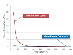
In trying to understand the maintenance of a heat exchanger, the discussion starts with the impact of the HTF’s viscosity. Figure 2 shows the temperature-kinematic viscosity curves for two types of HTF – a biphenyl-diphenyl oxide-based fluid and a terphenyl-based HTF – and shows that with increasing temperature their viscosity decreases. This means that, for cold starts, the viscosity and the resistance to flow through the systems tubes will be highest. Consequently, more power will be required to pump the HTF.
Therefore, an HTF with lower viscosity on startup will provide less resistance to flow and have better pumpability and heat transfer behaviors at low temperature. This is the first area in which maintenance is crucial because startup with a high-viscosity fluid can present a significant problem, particularly accelerated fluid decomposition from excessive and local heating, if flow is not sufficient. During startup, high-flow and gradual-fluid heating to the operating temperature defined in the safety data sheet for the HTF are important.
Temperature
Another factor to consider is continued overheating of the pipes that carry the HTF. The fluid closest to the internal surface of the pipework travels slightly slower in the boundary layer. If the internal wall temperature is too high, this can lead to the thermal decomposition of the HTF and longer-chain hydrocarbon (coke) formation, which can adhere to the pipe’s internal surface. This formation can be potentially fatal to the stability of the thermal plant because the hydrocarbons solidify and insulate the pipes. This in turn means the heat carrier is not cooled, leading to rapid scaling of the external surface and even melting of the pipe.
The decomposition of a fluid is largely driven by its temperature, although the mass and its distribution also influence this relationship. For the fluid in a system, its temperature varies by its location (for example, in the heater itself or in the return line heater) and the heat exchanger’s geometry. On this last point, Fourier’s law states that thermal resistance is proportional to the length of a pipe, provided the material properties of the pipe and its cross-sectional area remain constant.
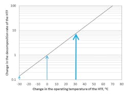
Figure 3 (page 18) plots temperature change, assuming zero to represent the operating temperature, against log plots of decomposition rate. It also shows that as temperature increases, a concurrent increase in the decomposition rate of the HTF occurs. Some interesting points should be highlighted from a maintenance point of view:
- Figure 3 shows that, for every 30ºC increase in the operating temperature of the fluid, approximately a tenfold increase in the decomposition rate of the fluid occurs. Conversely, the decomposition rate is decreased tenfold for every 30ºC decrease in the HTF temperature.
- From a maintenance perspective, Figure 3 implies that the most effective approach to reducing decomposition is to decrease the operating temperature. A decrease of only 10ºC may work to halve the decomposition of the HTF.
- While the operating temperature is different for each HTF, a uniform rate of decomposition is achievable. Fluid sampling to assess the decomposition rate against time is important and can protect the internal surfaces against coking.
Heat exchanger maintenance & cleaning
Many chemicals are used in the manufacture of HTFs – including silicone, aromatic and polyalkylene glycols – and these provide an alternative to water or steam because they can be used at lower pressures than steam and are less reactive and corrosive (further reduced with increasing purity). Unfortunately, all fluids will thermally degrade with extended operation at high temperatures. The focus is the formation of long-chain hydrocarbons (please see other publications5 for information on other degradation byproducts and how to test for their presence).
One of the most effective ways to gain insight into the internal health of a heat exchanger is to sample the fluid, ideally taking repeated fluid samples from multiple points throughout the system. This is especially true for large systems, such as concentrated solar power plants. Suggested sampling sites include the heater return and the heater outlet. From this sampling, operators can gauge the fluid condition in each area. Sampling has been extremely effective for assessing the current health of a system and for predicting future longevity, which is especially helpful when scheduling planned maintenance.
The overall goal of routine sampling is to sustain efficient operation and extend the working of the fluid and plant. Past research published in the journal of Applied Thermal Engineering5 tested whether the frequency of sampling was associated with the overall condition of mineral-based HTFs. Findings revealed that an HTF condition improved when it was sampled more often, with the best outcomes being observed when a fluid was sampled every three months. This highlights the importance of regular sampling and one of the advantages of having a regular, instead of intermittent, program of planned maintenance.
Best practice is to sample a fluid during operation rather than after system shutdown. This has many benefits for the manufacturer because the thermal plant does not need to be shut down, and interruption to production output can be avoided. It also means the system can be kept running and avoid unnecessary thermal degradation that could occur during startup. In addition, contractors are on and off the manufacturing site relatively quickly, and money and time are not lost supervising visitors.
Chemical analysis of a sampled fluid can be conducted remotely or on site and depends on the capabilities of the company commissioned to perform the work. Regular sampling and chemical analysis assesses changes in long-chain hydrocarbons and checks the following:
- Short-chain hydrocarbons, which are more volatile byproducts of thermal degradation
- Viscosity, which increases as the HTF thermally degrades and more carbon forms in the fluid and can drastically increase on shutdown
- Solid materials, which include the particles that circulate, may damage internal heat pipes, can accelerate the aging of the HTF, and can shorten the life of the fluid and the system in which it is flowing
- Oxidative/acidic state, which degrades the internal heater pipes in a system and occurs when the HTF contacts air
- Purity, which includes water and the soluble elements in water that can ingress during shutdown of the system and work as catalytic agents and accelerate fluid degradation
The last point to consider is the cleaning of a thermal plant. This invariably involves interrupting operations and losing production and profits. The type of intervention chosen as a corrective action depends on the findings of routine sampling and is normally driven by budgetary constraints and the decision of the end user.
For carbon, the easiest decision is the type of fluid chosen to fill a system. Often synthetic fluids will have lower purity, higher heat transfer efficiency and better thermal stability than a mineral-based fluid (see Figure 1). This means a lower propensity to thermally degrade and coke the heater. However, the choice of fluid is driven by the heat exchanger’s requirements and the cost of the fluid. Filling a new system can be expensive. When in operation, more cost-effective options are to filter the fluid and remove carbon formations from the system. This works in the same way as a sieve, with lower-sized pores working better for removing larger particles.
If chemical testing reveals coking of the heater, which could be the case if a fluid has been intermittently managed and coke has been allowed to build-up in the fluid and system, two options are available based on the extent of carbon levels. The first is to dilute the existing HTF with a virgin HTF, although this is only a short-term solution because most of the fluid will have started to degrade. The preferred option would be to drain the existing fluid, flush and clean the system with a suitable fluid, and then refill it with a virgin HTF, preferably a synthetic.
Fundamental take-home messages
- Use a high-purity HTF to help reduce thermal degradation.
- Use a low-viscosity HTF to avoid localized and accelerated coking and aging of the internal pipework, which can be caused by rapid heating on startup.
- On startup of the HTF system, ensure high flow and gradual heating of the fluid.
- Reduce the operating temperature to slow thermal degradation of the HTF and to identify a uniform rate of degradation.
References
“Heat Exchangers Market by Type (Shell & Tube, Plate & Frame, Air Cooled), Application (Chemical, Petrochemical, Oil & Gas, HVACR, Food & Beverage, Pulp & Paper, Power Generation), Classifications (MoC, Temperature Range & Fluid Type) and Geography – Forecast to 2021.” Nov. 11, 2016. http://www.marketsandmarkets.com/PressReleases/heat-exchanger.asp.
Wright, C. “What to consider when making the buying decision about a heat transfer fluid for your system: A report of the webinar hosted by Process Heating.” Journal of Applied Mechanical Engineering. 2016: 5 (1). DOI:10.4172/2168-9873.1000191. 191.
Lang, C., & B. Lee. “Heat transfer fluid life time analysis of diphenyl oxide/biphenyl grades for concentrated solar power plants.” International Conference on Concentrating Solar Power and Chemical Energy Systems (SolarPACES) 2014. Energy Procedia. 2015: 69. 672 – 680.
Wagner, Walter. Heat Transfer Technique with Organic Media. 2nd ed., Verlag Ingo Resch, 1997. p. 161 – 218.
Wright, C.I., Picot, E., & T. Bembridge. “The relationship between the condition of a mineral-based heat transfer fluid and the frequency that it is sampled and chemically analyzed.” Applied Thermal Engineering. 2015: 75; 918-922.
Author’s note: The author would like to acknowledge the writing support provided by Red Pharm communications, which is part of the Red Pharm company. Visit @RedPharmCo on Twitter.
Chris Wright is a research scientist for Global Group of Companies. He graduated from the University of Leeds in the U.K. with Bachelor of Science and doctorate degrees. His research focuses on the use and maintenance of HTFs in manufacturing and processing, which include the food, pharmaceutical, specialist chemical and solar sectors. Please contact the author for reference materials cited in this article. He may be reached at [email protected].
Global Group of Companies


