Overpressure protection against liquid overfill
Three incidents are commonly used to highlight the risks of liquid overfill upsets: 1998 Esso Longford,1 2005 BP Texas refinery,2 and 2005 Buncefield.3 Since 2005 there has been increased attention to the risks of liquid overfill.4 When identifying the risks and designing mitigations for liquid overfill upsets there are some considerations that are worth highlighting. While each design is unique and requires a full review, hopefully this article might provide some value to the engineering/operator teams conducting these reviews.
The liquid overfull upset
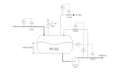
The level controller in Figure 1 will, on average, balance the volumetric out-flow (stream 2) and the inflow (stream 1).
Several upsets can result in the inflow exceeding the outflow, which will allow liquid inventory to accumulate and eventually overfill the vessel if the imbalance lasts longer than the available vessel surge volume. Some example upsets include:
1. Control valve CV-01 is driven 100% open due to a false low flow signal. The level controller will act to compensate, however in overpressure protection the protective mitigation provided by control actions is typically assumed not to occur. The normally occurring outflow could be credited. This upset could occur during a startup or some other non-normal operating mode where the outflow via CV-02 is at a minimum. The rate of accumulation would then be maximum inflow (CV-01 100% open) – minimum outflow (CV-02 at min position, or closed).
2. CV-02 is closed due to a false low-level signal from the level controller, or an instrument air failure if the valve is fail-close. During an instrument air failure if CV-01 and CV-02 are supplied by the same air-compressor they might be considered to both fail closed together. However, there is always a possibility of a local instrument air-failure that results in CV-01 continuing to operate normally, and CV-02 failing closed. During a startup pre-inventory of PV-01 it is possible CV-01 is at maximum flow (impatient operators), and therefore the accumulation rate would equal the maximum inflow.
Closure of CV-02 is also part of a more general upset where the P-01 pumps are blocked in downstream. It is important to consider if blocking in the P-01 pumps will consequentially lead to a liquid overfill case. When liquid overfill occurs during a blocked in case the PV-01 will be pressurized to the upstream pressure. Hence for downstream design pressures it is not double jeopardy to consider P-01 shutoff head simultaneously with maximum suction pressure to determine the required design pressure downstream. If this can occur before the liquid is brought up to normal operating temperatures then consideration of the maximum liquid specific gravity may also result in an even higher downstream pressure requirement.
3. Loss of pump P-01 prevents outflow from occurring. There may be other sources of pressure that exceed the design pressure of PV-01 downstream of P-01 that can back flow into PV-01. The accumulation rate would then be maximum CV-01 flow + back-flow. This back flow case is easily overlooked.
The back-flow contribution may not be insignificant, and there are several latent paths for the backflow to occur into PV-01. For example, some paths for back flow to PV-01 to occur are:
- Via the minimum flow control valve CV-03 (Figure 1). Unless there is logic to close CV-03 when P-01 stops then minimum flow controller will force CV-03 open when the pump stops.
- Via the pump warm up line.
- Via check valve – API 5215 discusses how a single check valve should not be credited to prevent over-pressure.
If two check valves are in series then when estimating the backflow via the equivalent orifice method5 it is important to check the maximum back flow at normal PV-01 operating pressure. This will determine the allowable surge time before overfill occurs. If PV-01 relieving pressure is assumed then the back flow and available surge time will be underestimated.
4. High upstream supply or destination pressures resulting in higher inflows, or reduced outflows, respectively.
5. Unexpected heat input can lead to expanded liquid volumes greater than normal. Such heat may be provided by introduction of hot streams, winterization coils, or possibly heat input from pump recirculation flows back to PV-01. The high level alarms/shutdowns should allow sufficient room for liquid expansion.
Potential consequences of overfill
The consequences of atmospheric release from a liquid overfill on the environment, and health and safety are generally easily recognized in a risk review. However, there are several less obvious unmitigated consequences that are worth considering:
1. Overpressure of PV-01 may occur if the source (upstream or downstream in the case of back flow) pressure exceeds PV-01 design pressure.
2. Liquid carryover may cause damage or unsafe conditions in downstream systems. A classic example is overfill of a compressor knock-out drum. However, there may be other consequences such as:
- Risk to vapor overhead piping if the pipes are not supported for liquid full operation or two phase operation in flashing services (such as LPG). Two phase flashing can result in flow induced, or acoustic vibrations that should be reviewed.
- For liquids such as LPG additional minimum design temperature considerations may be required. For example, liquid propane requires around a -45oC MDT, and ethane can require below -100oC MDT. If the vapor service lines do not have sufficient MDT then there can be risk of brittle fracture of the over-head systems.
- If the liquid is sent to the flare system either by a PSV, or a pressure controller (Figure 1, CV-04) then the flare system liquid handling capacity may be exceeded. It is important to consider the impact to the flare knock drum surge time, and liquid drop separation, and the liquid pump out capacity. Even if the vessel design pressure will not be exceeded during liquid overfill, pressure control valves such as CV-04 can allow unexpected liquids to flare during an overfill upset.
3. Public perception or company reputation can be damaged, and in some cases there can be criminal or civil consequences.
Considerations for design of mitigations
When mitigations are designed to prevent liquid overfill, there are several considerations;
1. When operator intervention is credited as a safeguard it is important to ensure there is enough time (10-30 minutes per API [5]) from the time the operator is first notified of an abnormal liquid inventory for the operator to recognize, and react to the upset. If operator response time is calculated from the LAH (pre-alarm) to the top of the vessel then operator procedures should clearly state that the operator must take immediate corrective action upon the LAH alarm. A typical action is to close the appropriate feed valve. The ability to remotely close the valve typically allows for a quicker operator response time. Even if there is sufficient time for operators to respond to a high level consideration of the operator failing to take action should be considered [5]. A HAZOP/LOPA is a good method to review the residual risks of an operator failure to act.
2. SIS functions to shutdown appropriate valves. These are usually independent of the LAH alarm. Additional independence can be achieved using a separate bridle, and different technology than the DCS LAH alarm to reduce risk of common failure modes. Some design considerations are:
- If the level uses a float (e.g. mag type) then ensure the float will indeed float by providing the full range of operating densities. Remember the bridle may be a different temperature than the vessel contents.
- It is recommended that the independent LAHH and LAH level instrumentations ranges overlap so that a deviation alarm may be activated if one fails.
- Ensure the SIS systems are properly tested to maintain the required SIL ratings.
3. The author has seen it suggested in different settings that a shutdown on high pressure may be used in place of a high level trip. The argument is that as level builds so will the pressure. I caution against this assumption for the following reasons:
- I’ve reviewed historical site level versus pressure site data for propylene storage vessels – there was no obvious correlation between level and pressure.
- If the vessel has a pressure control valve (CV-04, Figure 1) to flare then the normal control action will be to open the valve as pressure builds. This can result in the pressure not ever reaching the alarm point.
- The rate of pressure rise as enthalpy is packed into a vessel is a complex modeling problem that involves the rate of heat transfer to the surroundings, complex heat transfer interactions between the liquid/vapor surface. Prediction of the abrupt transition from not-liquid-filled to liquid-filled will be difficult to predict
- If the liquid rises at a slow enough rate the balance of heat exchange to the surroundings may compensate and the pressure may not rise as the level increases.
For liquid overfill a level transmitter is recommended. Although including a high pressure shutdown in addition to a level transmitter may be a reasonable additional layer of safety.
4. If a PSV is used to protect against liquid relief, then:
- Check if a set point adjustment is required to account for the liquid head.
- Ensure the PSV trim is acceptable for use in liquid or two phase flashing service. Even if the liquid overfill case is not governing in the orifice selection it is recommended to identify the liquid relief case on the PSV data sheet.
- Ensure piping stress considers the weight of liquid, two phase vibrations, slug flow etc.
- Ensure the flare liquid capacity is not exceeded. For LPG the orifice sizing is commonly governed by the hot relief cases that maximizes flashing through the PSV. However the colder relieving case will allow more liquid flow through the PSV, and reduces flashing. The cold relief case is frequently not identified – but it can become a governing case for evaluating the liquid overfill of the flare knock-out drum.
- If it is possible for vapor to be generated or introduced into the vessel when it liquid filled then the flow path for the vapor to the PSV must be considered. If the inlet piping to the PSV is below the top of the vessel then the vapor will have to displace the liquid between the source of vapor and PSV inlet. This can result in very large equivalent volumes of liquid that need to be pushed out of the vapor’s way.
5. The vapor lines might now require tracing to accomodate a liquid overfill.
Conclusion
While there is increased attention to the importance of overfill protection, the design considerations may not always be obvious. A complete and thorough risk review is required by an experienced team of operators, and design engineers to ensure nothing falls through the cracks.
REFERENCES
- Dawson, Sir Daryl Michael; Brooks, Brian John "The Esso Longford Gas Plant Accident" . Report of the Longford Royal Commission. Government Printer for the State of Victoria. June 1999
- U.S Chemical Safety and Hazard Invesigation Board. “Investigation Report”. U.S Chemical Safety and Hazard Invesigation Board, March 2007.
- Buncefield Major Incident Investigation Board , “Buncefield Major Incident Investigation”, December 2005.
- Summers, Angela E., “Overfill Protective Systems – Complex Problem, Simple Solution”, AIChe Global Conference, 2009
- API Standard 521, “Pressure-relieving and Depressuring Systems”, Sixth Edition, January 2014
Jonathan Webber, P.Eng Alberta, is a process engineer for Fluor Canada and a subject matter expert in overpressure protection at Fluor. Jonathan obtained his master’s degree in chemical enginering from Mcgill University (Montreal), and his Ph.D. from Dalhousie University (Halifax). He can be reached at [email protected].

