Best practices for effective dust collection hood design
Dust collection systems are sometimes considered a necessary evil because they are required to clean the air but add nothing to the bottom line. As a result, dust collection systems are often under-designed, under-maintained and modified with little or no design-based consideration, each of which can contribute to poor dust collection system performance. Two main components are critical to dust collection system performance: the hoods and the fan. This article will focus on the best practices of effective hood design.
What is a hood?
On a dust collection system, hoods are canopies or covers located at the end of ducting branches. The hoods are connected to dust-generating equipment and remove fumes and/or airborne fugitive dust from the machinery or production process.
By design, a dust collection hood should collect 90% or more of the fugitive dust, but in actual practice, industry considers hoods that collect 30% of the fugitive dust to be performing pretty well. So, how do you go from 30% collection and capture to 90%?
When designing a hood or verifying if a hood is working optimally, following a few best practices can influence not only how effective the hood is, but also the volume of air required for effective dust capture. Several important design considerations are often overlooked or done incorrectly.
Hood design basics
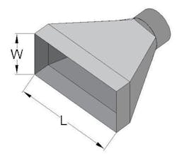
Hoods come in all different shapes and sizes and are used in every industry imaginable. Most dust capture hoods fall into one of three types: standard, slot, and other. The standard hood, as shown in Figure 1, is the most widely used and has a round or rectangular opening with a width-to-length (or aspect) ratio of the opening greater than 0.2 (see Figure 2). If the aspect ratio is less than 0.2, the hood is considered a slot hood. Since standard hoods are the most popular, I will use them as the example for further explanation.
The hood’s cross-sectional opening is referred to as the hood face and remains fixed for a short distance before converging to a duct connection or throat. The transition to the duct connection usually takes place over a 30- or 45-degree tapered angle, which can be symmetrical or eccentric.
The main objective in designing a hood is to effectively capture and collect fugitive dust. This requires that the hood be designed based on the actual physical, functional and influential parameters of the application and not be off-the shelf or one-size-fits most or using an arbitrary air volume because that is what is conveniently available.
Hood design methodology is explained in detail in the ACGIH Industrial Ventilation: A Manual of Recommended Practice and should be based on the appropriate theory, formulae and calculations for the hood and application. For a standard hood, the formula for calculating the airflow requirements is:
Q = V(10X2 + A)
Where:
Q = required air volume (cfm)
V = capture velocity at distance X from the hood (ft/min)
X = dust source distance from hood (ft)
A = cross sectional area of the hood (ft2)
Each of the input parameters listed in the hood design formula affects the overall air volume requirement differently. Before designing the hood, you must determine several things, the first being where the hood should be located.
Hood placement
Since the primary objective of hood design is dust capture, it should be intuitive to place the hood where the dust is being produced. This sounds obvious, but hoods are often placed where it is convenient for operations and maintenance, where the hood easily fits, where dust is leaking out of the equipment, where dust is accumulating, or just where someone thinks it needs to go. Most often, these locations are not where the dust is being produced.
A fugitive dust source may be considered at a set location, but it also must be considered where the dust is going beyond the source. When the dust is produced, does it just float straight up, or is it going off in another direction? Sometimes the path of the dust can be altered by movement in the process, such as high-speed trajectory off a grinding wheel or migrating due to pulsing air surges in the process. Whichever direction the dust is traveling should be where the hood is located, because it is almost impossible to collect dust that is traveling in the opposite direction of the hood.
Hood parameters
The next step of hood design is to determine the hood’s physical parameters. This is usually determined by the equipment or process interface: where the hood is attaching and/or the shape of the process component to which the hood will connect. The airflow equation shows the linear relationship between the hood’s cross-sectional area and the air volume. The bigger the hood, the more air required.
When determining the hood’s size and geometry, it is also a good idea to determine if any containment or enclosures around the hood can be added. Fully or even partially enclosing a dust capture area can greatly reduce the required air volume and improves the hood’s reliability. Enclosures assist with directing the dust into to the hood and reduce external air influences — such as HVAC vents or fans — that may blow the dust away from the hood face.
External air influences, along with the process movement, affect the capture velocity. Capture velocity is the required air velocity at any point in front of the hood that is necessary to overcome opposing air currents to capture the dust and direct it into the hood.
Determining the capture velocity is a prerequisite to calculating the air volume needed. The best way to determine the capture velocity is to use an anemometer to measure the air/dust speeds both at the source and in the surrounding area or to use equipment or process information to calculate it. If neither of these options are possible, industry guideline ranges for various typical applications are available in the ACGIH Industrial Ventilation: A Manual of Recommended Practice.
Hood distance from dust source
The final contributing factor to consider for hood design airflow calculations is how far the hood is located from the dust source. Ideally, the hood should be located as close as possible to the dust source without interfering with process operation or maintenance or causing a safety issue. The further the hood is located from the source, the larger the volume of air required to collect the dust. The airflow equation shows that each unit of distance (X) between the hood and the source increases the required air volume by a squared factor. With this exponential relationship, it does not take long before the required air volume gets out of control.
Often, the distance from the dust source is not considered when sizing a hood, and the hood airflow is arbitrarily selected — say 500 cfm (14.2 m3/min) — due to assumed generalizations, HVAC design concepts, or because that was the air volume used in the past. The following example demonstrates the effect distance has on air volume requirements.
If a hood has a cross-sectional area of 1 ft2 (0.09 m2) and the surrounding air velocity (capture velocity) is relatively still at 100 fpm (30.5 m/min), at the generalized 500 cfm (14.2 m3/min) of airflow, the hood should be located about 6 inches (152 mm) from the source. However, if the hood is installed 3 feet (0.914 m) from the dust source, it would require 9,100 cfm (258 m3/min) of airflow to achieve the same level of dust capture. This is a big difference! If you used this methodology on a dust collection system with multiple hoods, the total system air and design requirements would become massively excessive.
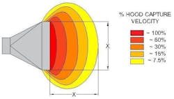
It is not always possible to locate the hood close to the dust source but how far is too far? In theory, there is no maximum distance the hood can be from the source, but as the example shows, the air volume quickly becomes very large and impractical. When dealing with standard capture velocity fugitive dust and typical hood flow, once the hood distance from the source is equal to or greater than the long-side rectangular dimension of the hood, the hood’s effective capture is reduced to almost zero percent, as shown in Figure 3. Increasing the capture would require dramatically increasing the airflow.
In limited specific cases, it may be advantageous to locate the hood further away from the source. One such case is when an easily migrating fine dust is liberated from a bulk material handling application, a closely located hood could extract a portion of the product into the dust collection system. Additional distance can reduce the immediate capture velocity close to the material so that the hood only captures nuisance fine dust.
The other scenario for extended hood distance is when the dust being collected is travelling faster than the hood can collect it. If dust is propelled directly into the hood faster than the airflow can remove it, one of three things can happen. The first, and ideal, situation is that the hood removes all the dust. However, if the dust is moving too fast for the hood, the dust will likely either fill the hood full of material leading to a blockage or plugging of the hood throat or, alternatively, hit the inside of the hood and bounce out. Either way, dust will likely end up on the floor or on other surrounding surfaces and not in the dust collection system. To ensure that the hood can collect the dust in this scenario, you must either increase the air velocity at the hood (which increases the system design requirements) or place the hood at a distance where the dust has decelerated to a point below the air velocity in the hood.
Good enough is not good enough
As the interface between the dust collection system and the process or dust source, dust collection hoods should drive system design requirements rather than the reverse. Inadequate hoods limit dust collection system performance potential, which leads to the system falling short of optimal dust control and/or more demanding system design requirements and energy consumption. With proper consideration and evaluation of the dust source dynamics and application of established industry standard design guidelines, dust capture hoods can be highly effective instead of just “good enough,” which is never actually good enough.
Diane Cave is regional manager of Eastern Canada at Element6 Solutions. She has more than 20 years of experience working with the design, installation and retrofitting of dust collection systems in industries ranging from sawmills and grain installations to food and beverage and specialty chemicals. Her expertise covers all aspects of dust collection systems, from troubleshooting system issues to upgrading systems to meet current codes and standards. Diane has also assessed hundreds of dust collection systems for combustible dust hazards using the latest NFPA codes and standards and conducted her fair share of DHAs. She can also provide advice and design experience for explosion protection systems, vessel retrofits, Pred verification, static bonding/grounding, and vessel strength analysis. Diane has a degree in chemical engineering from Dalhousie University in Halifax, Nova Scotia.
Element6 Solutions


