Implementing a PVC-membrane ultrafiltration package plant
Stricter regulation of drinking-water treatment has led to rapid growth in the use of membranes to treat challenging water sources. More specifically, hollow-fiber ultrafiltration is gaining acceptance in drinking water production.
Conventional treatment of river water usually includes flocculation, sedimentation and filtration. The widespread existence of disease-causing parasites such as cryptosporidium, giardia cyst and oocysts in drinking water sources is a challenge for these conventional treatment technologies.
The inefficiency of conventional filtration plants when it comes to filtering out and disinfecting these parasites can make use of ultrafiltration technology very attractive. Ultrafiltration has proven to be advantageous in producing high-quality water, free from suspended particles, parasites and viruses. It also performs well in removing turbidity, iron (Fe), manganese (Mn), color and total organic carbon (TOC).
Ultrafiltration is a kind of membrane filtration in which hydrostatic pressure forces a liquid against a semi-permeable membrane. Ultrafiltration systems eliminate the need for clarifiers and multimedia waste streams to meet critical discharge criteria or be further processed by wastewater recovery systems.
Ultrafiltration package plants using PVC membranes can be a technology of choice for small communities that don’t have access to clean drinking water. Pretreatment with coagulant may sometimes be required, especially when the natural organic matter level is high in raw water derived from a river or lake.
Flow configurations
The term ultrafiltration is used to describe a membrane filter, ideally with a pore size of 20 nanometers or less, or in the range or 0.05-0.01 microns. The high separation efficiency of ultrafiltration membrane is attributed to its small pore size.
Ultrafiltration systems come in different configurations and modes of operation. The most common flow configurations for hollow-fiber membranes are "inside-out" and "outside-in." For an inside-out configuration, raw water is fed inside the membrane lumen and clean water travels from the inside of the membrane to the outside. An outside-in configuration is the opposite.
Pressure-driven ultrafiltration systems are operated either cross-flow or dead-end. Most UF package plants operate in dead-end filtration.
Recent advances in polymer science mean a wide range of materials are available for membrane construction. These materials vary widely in their chemical and mechanical properties. Typical membrane materials include cellulose acetate (CA), polysulfone (PSF), polyether sulfone (PES), polyacrlonitrile (PAN) and polyvenylidene diflouride (PVFD). The membranes are prepared by a phase inversion process with asymmetric structure. These organic membranes are normally sensitive to cleaning reagents.
Polyvinlyechloride (PVC) has proven to have a narrow pore-size distribution, excellent physical properties, and demonstrated resistance to chemical cleaning agents. The molecular weight cutoff (MWC) for PVC membrane is about 50,000 dalton and can be designed for a flux rate of 54-145 LMH depending on the raw water turbidity. After one month soaking in sodium hypochlorite (1000 mg/L), caustic soda (4% weight) and hydrochloric acid (10% weight), PVC membrane material has shown more resistance than PVDF membrane. This test was conducted at Arizona State University.
One example
A "package plant" incorporates all of the elements needed to implement ultrafiltration in the treatment of drinking water.
The core elements of the package plant are the ultrafiltration modules — constructed of hollow-fiber PVC membranes — and the PVC pressure vessel. A centrifugal pump delivers the trans-membrane pressure to drive clean water through the membrane. Manual or self-cleaning pre-filters remove particle sizes above 0.5mm. To backwash the ultrafiltration modules, a backwash pump, sized for twice the feed flow rate, and backwash tank are provided.
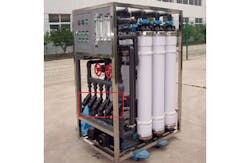
Automatic filtration operation and backwash stages are an integral part of the package plant and are achieved with actuated valves, control panel and programmable logic controller (PLC). Other package plant control components include feed, backwash and filtrate pressure indicators, rotometers to measure and control the feed and backwash flow rates and manual valves. Photo 1 shows a pre-engineered and automated drinking water ultrafiltration package plant. Since the ultrafiltration plant is a low-pressure system, interconnection piping is constructed of PVC or UPVC.
Package plant operation
In the case example under discussion, package plant operation entails a "dead-end" mode of filtration and inside-out flow configuration.
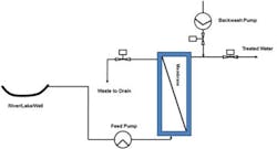
Operation is PLC-automated and involves three stages: filtration, flushing and backwash. In the filtration stage, the feed pump, sized for a maximum pressure of 3 bar, brings raw water to the system. The flow first goes through pre-filter, with 0.5mm openings, to remove large particles in the raw water that could plug the membrane.
The filtration stage takes about 30-60 minutes and removes solid particles, bacteria, viruses, colloids and other macromolecular organics, producing clean water.
Following the elapse of filtration time or given a sudden increase in trans-membrane pressure, the flushing stage starts automatically. In this stage, the feed pump continues to operate but the treated water valve closes while the drain valve opens, flushing out the membrane module. Flushing is necessary before any backwash starts, as it takes out all the cake built up inside the surface of the hollow-fiber membranes during filtration.
Back-flushing helps
Periodic back-flushing helps maintain the flux rate that is lost as the membrane fouls over time. A backwash pump, which has twice the capacity of the feed pump, turns on and the backwash valve opens. Back-flushing is achieved by reversing the flow, whereby the treated water enters the membrane’s lumen and travels to the outside, pushing backwards any particles deposited within the membrane pores.
Treated water from the membrane system is normally stored in a tank and used for backwashing. A backwash cycle normally takes about 60 seconds. The system reverts automatically to the filtration stage with its normal flux rate.
It is well known that it can be difficult to specify a pump that delivers exactly the design flow capacity. It is important to use flowmeters to manually adjust the feed pump and backwash pump flow rates during commissioning and start-up of the plant.
Chemical cleaning
Even with backwashing, ultrafiltration membranes will slowly foul. This is indicated by a gradual increase in operating pressure. To maintain system performance over an extended period of time, chemical cleaning is employed.
Chemical cleaning usually performed once a month should sterilize the membrane. Several chemical cleaning techniques can be employed, including chlorinated cleaning (only certain membranes can withstand this method), acid cleaning, caustic cleaning or use of a number of proprietary solutions. The acid cleaning recommended for PVC membranes involves use of 0.5-1% hydrochloric acid (HCl) solution. It is also recommended to use 0.5-1.5% of sodium hydroxide (NaOH) and 200ppm sodium hypochlorite (NaClO). These chemicals are circulated about 30 minutes through the membrane backwash system and then remain immersed for 1-2 hours.
Mohamed Ahmed Salah, P.Eng. is a licensed professional engineer in Ontario, Canada, with Larsen & Toubro Limited in Doha, Qatar. Larsen & Toubro Limited is a technology, engineering, construction and manufacturing company said to be one of the largest and most respected in India’s private sector.

