Piping systems are critical to many processing plants or facilities, and because of that they need to be designed and fabricated with precision and care. The efficiency and operational flexibility of many plants and facilities depends greatly on the ability, flexibility and efficiency to transport fluid through the piping to equipment and machineries functioning collectively. A piping system, owing to its crucial role of fluid transport, requires a systematic approach by various engineering tools and methods prior to its construction and commissioning. Piping should be supported to prevent failure due to various loading conditions such as self-weight, operating pressure, temperature differences and dynamic loads.
This article discusses piping stress analysis for processing plants with a focus on practical notes and useful technical guidelines. Complex formulations or numerical aspect of analysis are not discussed in favor of practical guidelines.
Stresses in piping systems: primary and secondary
For most piping systems including nozzles and branch connections, two major types of stresses are encountered. These are classified as primary and secondary stresses. Primary stresses are generated by primary loadings such as pressure and weight. The secondary stresses are associated with cyclic conditions such as temperature changes or imposed displacements.
There have been two major criteria for primary stresses. The hoop stresses due to internal pressure should be safe and within specified limits considering the wall thickness of the piping components, including any reinforcement. The sum of the longitudinal stresses due to pressure, weight and other sustained loadings should be less than the specified limit. These limits are also function of operating temperature. Allowable stresses are reduced at high or low temperatures.
Considering secondary stresses, there have been specific sets of allowable stresses that are repetitive and cyclic. One set is the range of (secondary) stress in a piping system subjected to thermal movements. The temperature range for this condition is the total range from minimum to maximum or vice versa. The region of highest thermal stress is usually where the system absorbs most of the thermal movements. This can be the place with highest temperature difference.
Relatively high initial thermal stresses may decrease with time because of plastic strains. However, thermal stresses might reappear, probably in reversed direction, when the operation is shifted to another operating case with a different temperature. This phenomenon forms the basic difference between thermal stresses (secondary stress) and pressure or weight stresses (primary stress). Plastic strains can release the magnitude of thermal stresses by a change in the shape of the piping center-line or permanent deformations. This change in the shape has no practical effect on the sustained pressure or weight stresses. For this reason, sustained stresses are typically limited to the lowest allowable stress at maximum/minimum normal operating temperature.
The degree of the above-mentioned effect will depend on the magnitude of the initial thermal stresses and the temperature. For example, the initial hot stress will in general decrease with time, and the sum of the hot and cold stresses will stay about the same. This sum is called the displacement (or expansion) stress range and is, therefore, independent of the initial state of piping during erection.
As a rough indication, for materials below the creep range, the allowable stresses are somewhere between 60% to 66% of the yield stress. Therefore, a rough safety factor of 1.5 - 1.6 was considered before reaching the yield. Too often, this is the bending stress at which plastic flow starts.
Nozzle loads
Nozzles serve to connect an equipment or machinery with adjoining piping network. These are relatively weak points which could be under considerable loads from piping. Nozzles whether nozzles of fix equipment (such as vessels, heat exchangers, reactors, etc). or nozzles of machineries (pumps, compressors, etc) are one of the most sensitive and critical components of piping stress analysis. A set of allowable loads for each nozzle in the form of forces and moments is usually provided by the manufacturer. Actual forces and moments imposed by the adjacent piping system on the nozzles should be less than the allowable limits. This is an important consideration particularly for delicate machineries that usually can only tolerate very low nozzle loads. This imposed many limitations on the piping systems connected to such machineries.
How to support piping?
The answer to this question needs many considerations and studies. However, a few rules are noted to start the supporting. Firstly, an optimum value of piping span should be estimated considering the weight load, temperature and pressure. As the focus is on weight load, rest supports should be inserted at each length of span calculated to restrict the downward displacements and associated stresses to recommended values. At this stage, restricting displacements in lateral and axial directions should be limited to only necessary locations.
Guide supports and stop supports should subsequently be used to limit the piping displacements in the lateral and axial direction, respectively. Anchor support and a set of supports limiting lateral movement should be specifically placed somewhere near sensitive equipment (such as a delicate machinery) to limit loadings on nozzles of such an equipment or machinery.
An important case is where the piping is lifted from the support (resting support, guide, etc). In numerical terms, this might be seen as reaction forces of zero magnitude. In that case, either those supports should be removed if estimated allowable span and other considerations allow this or adjustments of nearby supports made to account for efficient load distribution. Alternatively, if a support is needed in the location with lift-off due to any reason, for instance, to control modal/dynamic movements, a gripping or clamping supported (such a clamp) may be in that place.
How to reduce stresses and reaction loads
High reaction force is a major issue in piping and equipment nozzles. There are different methods to deal with this problem. One possible approach to alleviate the high stresses or high nozzle loads would be to accommodate thermal movements by changing the routing of the piping system by using a few additional bends, “Z” loops, U-turns, expansion loops or others. If not possible or not successful, other expensive options such as expansion joints and hangers might be used. These devices use spring effects to reduce the stresses, reactions and nozzle loads. These options impose considerable initial and operating costs to the piping systems and the plant. They reduce overall reliability. They should be used as the last option when other simpler and cheaper options cannot be applied.
Typically, hangers accommodate expansion along a vertical line only. They have been used to accommodate the weight of piping spool on the nozzles of equipment or machinery where rigid supports cannot be used due to thermal movement considerations. Expansion joints are restricted by a very high price range and thus expansion loops or similar turn are always the best options. Expansion joints can accommodate for all the axial movements, but requires special fittings, and many provisions. They have been maintenance-intensive. They are delicate pieces of equipment and only used in special circumstances.
Battery limits and connected piping
Often to have a clear picture of stresses and loads of piping systems of a unit and proper optimization of the piping, all surrounding and connecting piping systems should be considered. This is a critical consideration. How far of connecting piping should be included is a matter of debate.
The analysis of the piping in a unit should include a portion of the connected and surrounding piping systems so that the true response of the piping system under consideration is captured. The best approach is to model the interaction between all different piping, equipment and facilities as far as possible. The amount of piping to include in the model will vary from case to case but in general it should include:
- The piping up to at least three supports past a change in direction from the orientation of the battery limit of the unit under study. This is just an estimate, if required, a larger portion of the surrounding piping should be considered. For instance, sometimes, there are three guides or resting supports and there are configured in a way that axial movement can still be transferred to or from the unit.
- The flexibility of supports. When the flexibility of a support is considered, a support load and associated stresses are reduced. Such as reduction might be negligible or significant depending on many factors such as the flexibility of the support compared to the flexibility of the piping and overall system.
- The flexibility of the nozzle-shell intersection at any connection of equipment.
Case Study
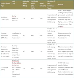
The case study is about a processing facility with many different piping systems from 48 inch (DN1200) to 1.5-inch (DN40). This is a high-pressure gas processing facility and each section should be operated in different hot or cold operating cases. There are 8 sets of operating pressure and pressures. Maximum operating pressure can be 130 Barg or 120 Barg depending on the section. Temperatures varies between -81°C to + 75°C depending on operating case and section. Table 1 shows combined and stress ratio of this system. Code allowable stresses are different in different loading cases and stress types. The minimum code stress is associated with sustained loading cases.

