Bulk material feeder types and applications
The main purposes for implementing a feeder within a bulk material handling system are to promote or activate flow, to control flow, and to measure or totalize flow. Some materials, due to their characteristics or the way they are stored, may not flow spontaneously and require a motive force to “activate” their flow. Conversely, some materials may be too free flowing and must be controlled to avoid spillage and flooding of the surrounding area. Additionally, some feeders are mounted on weigh cells, so they can monitor the throughput and totalized weight of the material being handled as they control flow. This can provide useful data for increasing a material handling system’s efficiency.
Typical feeder applications include:
- Emptying bins or hoppers;
- Feeding downstream conveyors;
- Reclaiming material from stockpiles;
- Directly discharging material from stockpiles in reclaim tunnels; and
- Feeding processes at a controlled rate.
Feeders are widely used in a variety of industries, including mining, metallurgy, mineral processing, manufacturing, ports and marine, food, and pharmaceuticals and are available in a wide range of duty ratings, from light to super-heavy duty. Depending on the type, feeders can handle a significant range of particle or lump sizes, from powders to large, heavy rocks. And feeders are used on a wide range of system sizes and capacities, from very small food and pharmaceutical applications to very large mining, metallurgy, and loading and unloading station applications.
Feeder types and operating principles
Feeders achieve flow activation using three mechanisms:
- Shear force plus conveying (belt feeders, apron feeders);
- Reciprocating motion plus gravity (vibratory feeders, stockpile activators, bin activators [also known as draw-down hoppers]);
- Pushing or dragging (screw feeders, rotary plough feeders, drag chain feeders, reclaim feeders).
Note that some feeder applications also require the use of shear force at the hopper outlet to activate flow.
Shear force plus conveying
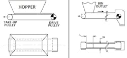
Belt feeders. Belt feeders are similar to belt conveyors in terms of their componentry and design. They consist of pulleys (typically two), a drive unit, a take-up unit, idlers, and a belt. Belt feeders are usually configured horizontally and are most commonly used to empty (draw down) material from within a bin or hopper (Figure 1). The bulk material is progressively removed from the bin or hopper through shear forces applied to the material by the belt.
Belt feeders are run at low belt speeds (relative to belt conveyor belt speeds), typically in the range of 0.25 to 0.5 m/s. Accordingly, they utilize much wider belting than a belt conveyor carrying the same capacity (tph). Belt feeders cannot run at higher speeds because they impart considerable force on the material to remove it from the bin or hopper. The slower speed also ensures more accurate material flow control.
Another control method for the flow of material on a belt feeder is the use of a profile plate or shear bar, which is essentially a volumetric capacity control. This is a steel plate or bar placed above the belt line just outside the leading edge of the discharge from the bin or hopper. The height is calculated based on the required cross-sectional area of material to be transported on the feeder.
Belt feeders are typically inserted into a system at the loading point of a belt conveyor. They are available in a wide range of ratings from light to super-heavy duty. Accordingly, they appear in many industries. Super-heavy-duty belt feeders are most commonly used in applications such as mines handling large, heavy rocks, whereas light-duty belt feeders are often used in manufacturing or even food or pharmaceutical applications.
Apron feeders. Apron feeders are like belt feeders in terms of operating principle but differ in terms of construction. Where a belt feeder utilizes a belt to carry the material load, an apron feeder utilizes steel plates or pans that are mounted on heavy duty chains. This resembles something like a tank track, similar to what is used on front-end loaders and dozers as “wheels” to produce motive force. The chains act like the belt in a belt feeder, providing the motive force, and are driven by large sprockets that are connected to a drive unit via a drive shaft.
Apron feeders typically handle medium to large rock particles, allowing finer particle sizes within the flow to pass through the gaps between the plates (or pans). This can result in significant spillage through the apron feeder and the buildup of fine material below. Accordingly, apron feeders are fitted with “dribble” conveyors that are essentially slow-moving, low-capacity belt feeders that capture the finer material and transfer it to the apron feeder’s discharge point.
The main differentiator between apron feeders and belt feeders is that apron feeders are much better at handling high-impact loads and high-temperature materials than belt feeders. Apron feeders are typically used in heavy- to super-heavy-duty applications, such as mines sites or large train unloading facilities.
Reciprocating motion plus gravity
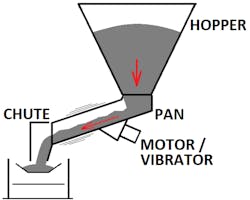
Vibratory feeders. Vibratory feeders consist of angled pans and a vibrating device (Figure 2). Vibratory feeders utilize vibration and gravity to provide the motive force to the material being transferred. Typically, an out-of-balance weight on an electromechanical device is used to generate reciprocating action, causing vibration and flow activation.
The angle of the pan must be calculated to ensure adequate material flow. If the pan angle is too shallow, the material may not move; if the pan angle is too steep, the material may flow uncontrollably. The frequency of the vibrating mechanism must also be determined to optimize flow.
Vibratory feeders are typically implemented directly below bins or hoppers to transfer material onto conveyors. With proper calibration, a vibratory feeder can achieve consistently steady flow, contributing to overall material handling system control and efficiency.
Vibratory feeders can be used in light- to heavy-duty applications. When properly calibrated, small vibratory feeders can be used to meter discrete items through a process, such as pharmaceutical tablets, while heavy-duty vibratory feeders can be used for emptying large ore bins. The feeder’s design and materials of construction are tailored to the application. In some instances, vibratory feeders fitted with specialized pans are used to sort or orient pieces for feeding into a detailed manufacturing or packaging process.
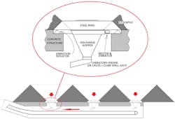
Stockpile activators. Stockpile activators consist of an angled annulus (ring) steel plate that is typically mounted below a stockpile (Figure 3). The concrete structure of the tunnel below supports the stockpile activator in the roof of the reclaim belt conveyor tunnel. A pulsing or vibratory action is activated through a drive motor and out-of-balance weight attached to the bottom of the annulus steel plate, which acts as a pulsing device and causes the material to flow. The pulsing action ensures that the material above “falls” at its natural rill angle (or angle of repose). An angled conical chute below the annulus steel plate directs material flow to a central location.
Stockpile activators are used to avoid ratholing, which is where a steep-walled hole develops in the material bed at the underground reclaim point, with the surrounding material remaining stagnant. The vibratory nature of stockpile activators also prevents material bridging over the reclaim point opening. A longitudinal stockpile may have multiple stockpile activators located along the length of the underground (tunnel) reclaim conveyor. Circular stockpiles may have a single unit at the center.
Below the hopper discharge, either an angled chute and clam-shell gate combination or a vibratory feeder can be used to control the material flow from the hopper and prevent material from flooding onto the belt conveyor below.
Bin activators. Bin activators (also known as draw-down hoppers) are similar in principle to stockpile activators. They are connected to the discharge point of a bin and are hung on suspension arms to allow the bin activator to move relative to the bin. A motor and vibrator are attached to the bin activator ring, which typically includes cross bracing inside the ring with an inverted cone to moderate material flow through the opening. The space between the bin activator ring and the bin is sealed with rubber that accommodates the vibrating motion. Bin activators are usually used with materials that have small to medium particle sizes.
Pushing or dragging
Screw feeders. Screw feeders consist of a round-bottomed enclosed casing, often with a top-mounted inlet at one end and a bottom-mounted outlet at the opposite end. In some cases, a screw feeder essentially fits along the bottom slot of a hopper, with the material in the hopper sitting on top of the screw. This is known as a live-bottom hopper. Live-bottom arrangements can include multiple screws in parallel, providing a greater footprint area to draw down material from the hopper.
For a single-screw feeder, the screw is within the casing, and the pitch of the screw flights can be graduated from the tail at the inlet end to the head at the outlet end to avoid compressing the material within the flights along the length of the screw. The pitch on the screws increases closer to the head end, allowing for efficient material flow.
Some screw feeders incorporate tapered screw blades, with the blades getting larger along the length, while others have tapered shafts to control the cross-sectional area of material being pushed at each point along its length. The screw shaft is kept in position with hanger bearings mounted at regular intervals from the top of the casing or standing bearings mounted from the bottom of the casing.
In all cases, the screw is driven by a drive unit mounted at one end of the screw feeder and connected directly to the screw shaft.
For regular screw feeders, material falls through the inlet via gravity. Material then collects on the bottom of the screw feeder casing and is pushed forward by the screw’s flights as the screw rotates. For live-bottom applications, the material sits on top of the screw (or screws) and is drawn down into the screw flights and pushed forward to the discharge.
Because screw feeders are fully enclosed, they are a good mechanism for dust containment, assuming that all flanged connections are adequately sealed.
Rotary plough feeders. A rotary plough feeder consists of plough blades, a plough drive unit, a long travel drive, and a mounting frame with wheels. Rotary plough feeders are used underneath hoppers with a longitudinal slot along the wall. The leading edge of the plough blades fit into the slot, and material falls onto the blades as they rotate in plan view and drag material out of the hopper through the slot. Material is then discharged directly onto a belt conveyor that runs parallel to the hopper slot. The mounting frame of the plough feeder straddles the belt conveyor and sits on rails that run down either side of the conveyor. Due to the arrangement, the conveyor is located within a tunnel or longitudinal chamber.
The plough feeder’s main application is to reclaim material onto conveyors. This type of feeder is most often implemented within the coal industry and can be used in medium to heavy-duty applications.
Drag chain feeders. Drag chain feeders are fully enclosed within a casing. At each end of the feeder is a sprocket (analogous to the pulley in a belt feeder) that drives a longitudinal chain with plates mounted to it at regular intervals. The material inlet is located on the top near the tail end of the casing, and the material outlet is located on the underside at the head end of the casing. As the chain rotates, the plates on the lower strand of the chain drag material through the casing from the inlet end to the outlet.
Drag chain feeders can have circular, square or rectangular cross sections depending on the application requirements. The casing must be shaped accordingly to minimize cross-sectional voids along the length of the feeder and maximize material dragging.
Like screw feeders, drag chain feeders are fully enclosed, making them good for dust containment. Accordingly, they are used for lower throughput capacities and smaller (sometimes powdery) particle sizes. Drag chain feeders are most commonly applied in furnace feed systems.
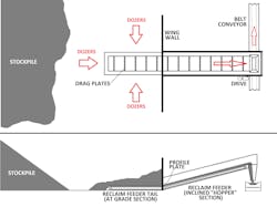
Reclaim feeders. A reclaim feeder (Figure 4) is a specialized drag chain feeder used to reclaim material from stockpiles and deliver the material to conveyors. Reclaim feeders consist of a drag chain within a housing and connected to a drive unit shaft via sprockets. The tail section of the reclaim feeder is horizontal and is placed at grade. The reclaim feeder then inclines and elevates the material high enough to be easily discharged onto a belt conveyor. Between the feeder’s tail and inclined sections is a wing wall that prevents spillage that can occur from the pushing of material by dozers. The wing wall includes a profile plate to regulate the cross section of the material passing through to the feeder’s incline section. The inclined section has side walls that contain material and prevent spillage.
Reclaim feeders are located near the edge or toe of a stockpile and are fed by front-end dozers pushing material over the tail sections. The material is then pushed by the blades on the drag chain conveyor and then discharged to a belt conveyor for further handling and feeding into a system or process.
Reclaim feeders can be used in high-capacity applications for materials with medium to large lump sizes.
Feeder selection and typical design considerations
Not all feeders are suitable for all applications, hence the wide variety of designs. A technology selection should be carried out at the start of a study or project to determine which feeder type is best suited for the application. When selecting a feeder type, consider the following:
- Application/operating parameters
- Location
- Available real estate such as land and space within a plant
- Duty rating (light/medium/heavy/super heavy)
- Material characteristics, including particle size, flowability, abrasiveness and moisture content
- Capacity or throughput
- Height and length to move the material
- Dust and/or spillage considerations or restrictions
- Process considerations such as metering, flow sorting or outlet valve requirements.
Noel Wallace is bulk materials handling manager at Hatch.
Hatch


