Six main reasons for dust collection system failure
Key Highlights
- Proper hood design must incorporate Containment, Capture and Control to effectively manage dust emissions at the source.
- Correct duct sizing and manifold design are critical to maintain adequate airflow velocities and prevent dust accumulation in the ductwork.
- Selecting the appropriate dust collector involves ensuring sufficient filter area and proper filter media to handle airflow without blinding or clogging.
- Efficient material discharge systems, such as properly sized rotary valves or slide gates, are essential for continuous dust removal and system performance.
- Choosing a fan with a performance curve that matches system requirements prevents airflow reduction and maintains dust collection efficiency.

The basic purpose of a dust collection system is to control dust emissions from designated sources within a manufacturing or processing plant. Having designed, audited, and/or improved more than 2,000 dust collection systems over the last 50 years, I have literally made a living either correcting or replacing systems that fail to achieve this basic purpose.
However, dust collection system failure and its associated costs and safety risks are entirely avoidable. Six main causes lead to the vast majority of dust collection system failures, and by being aware of the major sources of failure, end users can take the necessary steps to avoid them.
1. Improper hood design
A dust collection system can consist of the best equipment and be designed with proper ducting arrangements but still fail to collect and/or control the dust emissions generated at the dust sources. Under these conditions, the failure is typically due to improper hood design.
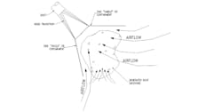
Decades ago, I developed the three Cs of proper hood design: Containment, Capture and Control. This approach to proper hood design has been adopted by multiple experts, institutions, and the National Fire Protection Agency (NFPA). Unless the design incorporates all three of these functions, the resulting hood will be ineffective.
For effective containment, the hood must limit the space where aerated dust can be emitted. However, this does not mean full enclosure, as full enclosure results in unwanted accumulations, which are a hazard with combustible dust and can lead to multiple problems.
For effective capture, the hood design must direct the incoming airflow through the aerated dust, allowing it to be captured by the airstream. This implies that there must be a reliable, continuous air supply, which is often not considered in the hood design.
For effective control, there must be sufficient airflow and energy to both capture the dust emissions and then direct the airflow into the ducting and, eventually, the dust collector. To operate properly, each hood must have an adequate minimum level of induced airflow (energy) to ensure that the dust is collected at all times.
2. Improper duct sizing and manifolding
A dust collection system is typically designed with multiple hoods to collect dust from multiple dust sources. Unless the ducting that runs from these hoods to the dust collector is correctly sized and manifolded, dust can accumulate in the ducting and compromise the desired air distribution. Over time, this can result in system failure. Improper ducting guarantees both insufficient dust control/collection and dust accumulation in the ducting.
In my experience, a minimum of 4,000 fpm of airflow is required for typical non-combustible dusts and 4,500 fpm of airflow for combustible dusts. The airflow requirement is higher for combustible dusts due to the NFPA requirement that dust velocity be adequate to keep the ducts clean during normal operation.
The ducting connected to any of the hoods must be sized to guarantee adequate duct velocity, and where two or more duct branches meet, the differential pressure (i.e., the energy required to induce the desired airflow) must be the same for each branch. This is the key to proper duct sizing and manifolding. Any branch connection that does not achieve this requirement will result in air distribution problems within the system.
The Balanced-by-Design method of dust collection system design (discussed later in this article) is a proven method of matching airflows and energy requirements in a dust collection system and has been in use for many decades.
3. Incorrect dust collector selection
Whether the dust collection system uses dry separation or wet separation, it is imperative to select the proper dust collector. Most dust collection systems are dry systems that do not require a wet scrubber. However, wet dust collection systems must follow the same general requirements as dry systems. (Note that NFPA calls all such devices Air-Material Separators (AMSs).) Failure to select the proper dust collector will guarantee problems, if not complete system failure.
While many factors should be considered when selecting a dust collector, the most common mistake is underestimating the amount of filter area required to provide long-term and reliable operation. The value most purchasers of dust collectors use for filter area is air-to-cloth ratio (or air-to-media ratio). What is not readily understood is that this value is more properly stated as the air velocity through the filter media (i.e., filter velocity). If you divide the volume flow by the square feet of filter area, you get feet per minute (fpm), which is velocity.
A velocity (or ratio) that is higher than the filter area can handle causes dust to embed in the filter media, rapidly blinding the filters and leading to a corresponding reduction in airflow through the dust collection system and eventually requiring excessive energy to pull the air through the filters. Depending on the type of fan package, this inherently prematurely reduces the airflow through the system. In my experience, most poorly performing dust collection systems do not have sufficient filter area in the dust collector.
The type of filter used in the dust collector is also a factor. In my experience, cartridge filters should be limited to an air-to-media ratio of 1.5:1 or less, while bag filters should be limited to an air-to-media ratio of 5:1 or less for most dust collection applications. These are rules of thumb and subject to deviations based on application conditions. Cartridge filters are limited in their performance due to the physical construction of the media, as excessive airflow through a pleated cartridge filter results in plugging of the pleats.
4. Inadequate collected material discharge
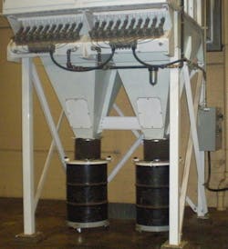
The collected material discharge from the dust collector is an often ignored but critical part of a successful dust collection system. Dust collectors are not designed to be storage bins, and the collected material should be handled on a first-in, first-out, basis.
Too often, an undersized rotary valve or automatic slide gate/butterfly valve is used to empty the dust collector of collected dust. This is usually a major mistake.
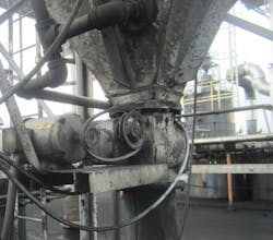
I have observed many dust collector hoppers pocked and dented with sledgehammer marks from operators trying to encourage material flow through an undersized rotary valve or slide gate. If you find yourself permanently keeping a sledgehammer near the dust collector discharge, this is a bad sign.
A manual or automatic slide gate or butterfly valve can be a successful approach if the valve is sized properly and is directly connected and sealed to a waste container to allow for direct discharge into the container.
If you anticipate material discharge problems from the dust collector (usually due to material characteristics), the discharge method should be designed to provide as large an opening in the dust collector hopper as possible, combined with a flared-trough screw conveyor and a properly sized rotary valve.
5. Improper fan selection
The purpose of a dust collection system fan package is to provide the necessary energy, under all normal operating conditions, to induce airflow into the hoods, through the ducting, through the dust collector and, finally, through the fan package. A key to that statement is “under all normal operating conditions.”
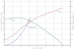
A typical dry dust collection system is not a steady-state system. Over time, the energy required to maintain adequate airflow in the system increases, causing the fan performance to “back up” the curve to achieve higher differential pressure. But with a centrifugal fan package, this also results in reduced airflow.
Major problems occur when the fan performance curve is too “flat,” as shown in Figure 8. This results in a comparatively large reduction in airflow when more differential pressure is required. Assuming a system design of 19,000 acfm with clean filters, a differential pressure change of 3 inches water gauge due to dust accumulation on the filters over time can result in 4,000 cfm or more in reduced system airflow. This is a major reduction in a system designed for 19,000 cfm and would likely result in air velocities that are too low to keep the captured dust entrained in the conveying airstream.
To prevent such a scenario, always select the fan package by matching its performance curve with the system requirements.
6. Improper system engineering and design
The single most common cause of dust collection system failure is improper engineering and design. If a dust collection system is properly designed by qualified personnel, all the other causes of failure discussed in this article can be avoided.
Almost invariably, when called upon to improve a poorly performing dust collection system, I am informed that the system was “designed” by the local sheet metal shop, HVAC contractor, plant maintenance, or most junior engineer in the facility. Such “designers” are rarely qualified for the job and frequently produce systems that exhibit all five of the other causes of failure discussed in this article.
The only proper method of dust collection system design is the Balanced-by-Design method, which ensures proper air distribution, duct velocities, and airflow at the dust sources. This method is based on physics and fluid dynamics rather than artificial methods such as “balanced-by-slide-gate” or “balanced-by-bleed-in.” When multiple dust sources are involved, these artificial “methods” always fail.
About the Author

Jack Osborn
Senior Project Engineer
Jack Osborn is senior project engineer at Airdusco EDS and a member of Processing’s editorial advisory board. He has more than 50 years of experience in dust collection systems, centralized vacuum cleaning systems, pneumatic conveying systems, and all types of bulk handling systems. He has either designed or evaluated (e.g., engineering studies/audits, performance testing, etc.) more than 2,000 dust collection systems during his career and is a participating member of all six NFPA combustible dust committees.
