Screw feeders are commonly used to control the discharge of bulk solids from storage hoppers. Hopper design was somewhat of a black art until the 1960s, when Andrew Jenike published his theory of solids flow. As well as providing a scientific basis for hopper design, it introduced the concept of mass flow.1 This technology was introduced to the UK at the first international conference on the subject at Bradford University in 1967. Inspired by this and Alan Roberts’ award-winning paper, “The performance of grain augers,”2 I presented a paper titled “The entrainment pattern of screw hopper dischargers” at a conference in Boston in 1968.3 This paper emphasized the importance of contact friction of the product handled on the extraction mechanism. Screw feeders developed increasing applications as the technology spread through industry as, in addition to providing a reliable, controlled rate of discharge, they offer many important operating and process benefits compared to other feeding devices, such as:
Allowing plane flow. Ratholes cannot develop in plane flow, and reliable discharge takes place through widths smaller than circular outlets.
Providing more storage capacity and/or saving headroom. Long outlet slots and shallower walls available in plane flow enhance the storage capacity of a hopper in both mass flow and funnel flow.
Rectifying segregation that occurs during filling. Extracting from different regions of the hopper remixes the contents during discharge.4
Reducing the prospect of flushing. The lower flow velocity in the discharge channel reduces the counterflow of air rising to escape from a fluidized product, allowing more time for the material to settle to a stable flow condition.
Reducing blockages by lumps. Agglomerates and lumps are less likely to come together to create a stable blockage in plane flow than in funnel flow, and even if lumps form, they do not block the whole channel and the stoppage may be eroded by the adjacent flow.
Providing a more uniform residence time. Whereas mass flow will avoid indefinite residence time for some storage regions, spreading the flow channel diffuses the flow rate between different regions of storage.
Delivering a more consistent density. A consequence of more uniform extraction is that the material settles more evenly and will adopt a more even density, which is important for many feeding operations.
To secure these benefits, the extraction rate should be progressive along a hopper outlet length that is at least three times greater than its width. As the length of the hopper outlet slot is usually shorter than the length of the hopper body, the extraction rate should be greater at the starting and finishing ends of the outlet slot than in the central section to secure a more uniform residence time for the hopper contents. This pattern is secured by various changes in the construction of the discharge screw. Common methods are to vary the pitch and diameter of the screw or the screw’s center shaft.
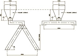
The ability of a feeder to reverse is sometimes used to reject unsuitable product or deliver to an alternative location. However, the many flow and operational benefits of a plane flow hopper cannot be provided in both the forward and reverse direction of feed by a conventional feeder because incremental extraction cannot be provided in both directions of discharge. Nevertheless, considerable headroom saving may be made with short inlets compared to the alternative common practice of fitting a diverter valve and inclined bifurcated chute (Figure 1). Unfortunately, many important benefits of plane flow cannot be achieved with a short outlet.
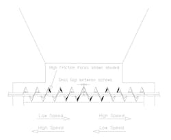
While uniform pitch screws can be used to extract from elongated hopper outlets, they preferentially extract from the initial section exposed to the hopper contents and then, within a short axial length during which the screw volume fills with material, the contents are carried along the hopper outlet under a bed of static product (Figure 2). Apart from negating the prospects of mass flow, this form of extraction induces extra shear on the product.
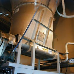
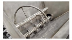
It is apparently impossible to secure progressive extraction pattern in a long slot outlet by reversing the screw. However, a unique, award-winning design by Ajax Equipment achieves this, enabling the feeder to progressively extract material along an elongated outlet slot when running in either forward or reverse direction and, optionally, deliver to two alternative outlets by simply reversing the drive. The design accomplishes this task by exploiting the mechanics of a screw feeder. Contrary to a popular assumption, the axial transfer of a helical screw is not the volumetric capacity but depends on the value of contact friction between the bulk material and the working face of the screw flight.
This frictional feature allows the extraction capacity of a screw to be varied by changing the surface of the flight to different frictional values. Selectively constructing the flight with a high friction surface on the initial region exposed to the hopper and a low friction surface further along the hopper outlet results in extraction taking place in both regions.
As a screw does not fill completely in one pitch, because flow stresses are transferred to the following section, extraction takes place over approximately 1.5 pitches of a screw with uniform construction. With a subsequent region behaving similarly, extraction can take place over an outlet length equal to three pitches. This is adequate to secure the many benefits of plane flow.
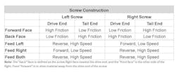
The initial section of the working face of the flights when the screw delivers in one direction can be modified on one face and the screw section under the opposite end of the hopper outlet to be similarly increased in friction on the relevant side of the flight face. As these flight faces are not a sliding surface for the material when the screw is rotating to bring material towards this end of the hopper, and the opposing end has the reverse effect, the benefits of progressive extraction are gained when delivering to either end.
Exploitation of the less efficient axial transfer generates a two stage increase in extraction capacity along the screw length when working in either direction. This technique permits a single screw to generate ‘live’ extraction over a hopper outlet slot length of over the three screw pitch lengths. This offers a more reliable flow route and a massive headroom saving over the conventional two-way valve and bifurcated chute normally fit to deliver to two different receiving points.
Not only this; a variant on the design, which includes an extra drive, will serve a longer length of outlet slot and also allow either outlet to be served individually, or both at the same time, without changing the required delivery rate.
The means that the solution to overcome the limited “live” extraction length of a single screw for reverse feeding is to install twin, cantilever-mounted extraction screws with variable face friction flights on both sides in the manner previously described in a common casing, such that they have independent drives and fit end-to-end under the center of the hopper outlet (Figure 3). By regulating the separate drive speed such that the speed of rotation of the second screw in the direction of motion is twice that of the initial screw, the feeder can serve an effective “live” flow outlet slot of four to six times the screw pitch.
A further benefit of this arrangement is that the screws can be employed to deliver to either outlet, or to both receiving ports at the same time, without jeopardizing the “live” extraction of material over the total slot length. The amount of material that the screws are delivering to either end is determined by the screw construction nearest the receiving outlet, whether feeding in one direction or both. Once the relative speeds are set for the drives in each direction, no adjustment is needed to secure the selected discharge rate; whether feeding to either or both receiving points.
Selection of required delivery is given by pressing buttons on the controller for “left,” “right,” or “both” and then “start.”
For optimum performance and to secure the full benefits of mass flow, the feeder construction should be based on the value of contact friction, the detailed proportions of the screw and flight construction, and the hopper shape relative to the feeder inlet.
References
1. “Flow of solids.” Andrew Jenike. Univ. Of Utah. Bul. 123. 1965.
2. “The performance of grain augers.” Proc. I.Mech.E.176. (No.8).165-194. (1962).
3. “Entrainment pattern of screw hopper dischargers.” ASME 1968 Boston Conference. Paper No.68-MH-2.
4. B.M.H.B. Book — “User Guide to Segregation” (Available from Ajax).
Lyn Bates is chairman at Ajax Equipment. For further details on this novel technique or advice on feeders, segregation, and hopper discharge, contact [email protected].
Ajax Equipment
Sponsored Recommendations
Sponsored Recommendations
