Bulk solids feeders: The importance of flow pattern

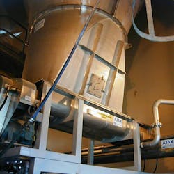
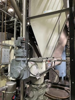
Feeders are commonly fitted to bulk storage hoppers and silos to control material discharge. They come in all sizes and materials of construction and are often purchased independently from the storage container. However, for best results, the feeder and hopper should be considered as integral to each other, as the performance of the system depends on the relationship between the extraction pattern of the feeder and the construction of the hopper.1 Classical technology classifies the flow pattern developed in the hopper as being either “mass flow” or “funnel flow,” distinguished by whether all the material moves (mass flow) or not (funnel flow) during discharge. In practice, a useful compromise called “expanded flow” may be employed to secure the flow benefits of mass flow in the hopper outlet region when the contents are stable over time and when segregation is not an issue. There is also an important difference between a flow pattern with a large velocity gradient throughout the flow channel and one with a more even velocity in all regions.
Like many purchasing decisions, hopper selection may focus on capital cost. This can lead to the choice of a gravity-flow design rather than a design with a plane-flow outlet section as a plane-flow hopper requires a feeder that collects material from an extended length of hopper outlet slot. However, plane flow offers many advantages that can outweigh any difference in initial cost. Also, while gravity flow directly from a conical hopper outlet may be adequate for discharge in many applications, a feeder will provide control over the discharge rate and so is often fitted to conical outlets anyway. Feeders provide many other advantages as well, some which may dominate the selection criteria. These advantages include the following:
1. Control of feed rate
Because feeders can vary the extraction rate by speed control, they permit a wide range of discharge rates. Linked to a control system, the output may be adjusted to suit batch quantities or loss-in-weight control for accurate dispensation. More accurate control of batch weights may be achieved by reducing the discharge rate as the target value is approached.
2. More stable bulk density
Bulk material attains a more stable bulk density in the larger flow channel moving at a lower flow rate to a feeder. The counter-flow velocity of the material to that of excess air escaping from the material carried down with the material is reduced, allowing more time for air to escape from fluidized powders and increasing the rate at which the material settles to a stable density. Consistent density of discharge is important for items such as soap powder and cereals that are dispensed by volume yet sold by weight and so include a “giveaway” amount to ensure that the contents of a pack are not less than the weight stated.
3. Enhanced discharge capacity
A feeder can provide a much larger flow area than the outlet of a conical hopper, and a plane-flow hopper has a smaller velocity gradient across the flow channel. This enables a slot outlet to discharge more volume in a less dilated bulk material condition than a circular hopper outlet.
4. Increased hopper holding capacity
Two factors enable additional volume to be held within a given headroom:
- The extended outlet length and plane-flow hopper construction increases the holding capacity of the hopper compared with a cone.
- The plane wall inclination necessary to generate wall slip for mass flow is approximately ten degrees lower than the inclination needed for a conical construction.
The combined effect is that more capacity can be stored within a given headroom.
5. Reduced headroom requirements
The increased holding capacity allows the equipment to be designed to require less headroom, affecting both the site headroom demand and the height of the hopper filling equipment and access facilities. This feature may be crucial where headroom is at a premium by virtue of planning consent or site restrictions. Combinations of headroom saving and holding capacity may be chosen.
6. More uniform drawdown
In some applications, such as the discharge of dust hoppers and plate filters, the order of discharge of different regions of the hopper content is irrelevant, providing that the material completely clears. However, products that are sensitive to time consolidation or caking should have a residence time that is as even as possible, not only by mass flow, but with the smallest local velocity variation practical.
The velocity gradient across the cross section of a plane-flow hopper served by a well-designed feeder is much lower than that in a conical channel. This provides a more uniform residence period for the hopper contents, which is a useful attribute for preventing the early discharge of fluidized products in narrow flow channels and for materials that are sensitive to time consolidation or caking in extended storage. The extraction profile of the feeder can also be arranged to suit the hopper outlet slot length and the cross section of the hopper body.
It should be noted that the initial exposure of the feeder screw to the contents of the hopper will transfer the total swept contents axially, while subsequent sections can only extract and transfer marginal increases in capacity. Compensating changes in the feeder screw’s pitch and shaft diameter can be made to best match local extraction to the optimal pattern.
7. Redressing segregation
The velocity gradient in the converging section of a conical hopper preferentially extracts material from the center, a region that tends to segregate radially during the filling process. This phenomenon is more dramatic in situations where the discharge takes place at the same time as the hopper is being refilled, as with continuous processes that require supply and demand to be synchronized such as the supply to packing equipment.
By contrast, extraction along the length of a slot outlet will mix material from different radial regions of storage and, combined with the more even drawdown characteristics of a plane-flow channel, more thoroughly reflect the homogeneous composition of the bulk material loaded into storage.
8. De-aeration characteristics
An unfavorable feature of conical flow for de-aeration is that the velocity gradient across the flow channel is higher than in plane flow. This feature results in a lower residence time for fresh material loaded into the hopper and a higher counter-flow velocity against air rising to escape. These factors combine the tendencies to carry air down with the product and increase the danger of “flushing.”
By contrast, the larger flow area and lower velocity gradient in plane flow means the material has longer to de-aerate, and the settlement to a stable flow condition is more efficient because of the higher effective air escape velocity.
An effect that leads to flushing is that freshly loaded material in a fluid condition exhibits hydrostatic pressure and, as a result, will preferentially displace more settled material, which has a lower lateral pressure, to enter the flow channel. This behavior results in fluid material from the surface progressively penetrating the material bed until it nears the hopper outlet, at which point it will burst through and flush uncontrollably. The larger flow area in a plane-flow hopper, with a lower flow velocity and reduced velocity gradient in the flow channel, allows more time for the material to settle to a stable condition and radically reduces this hazard.
Fine materials also tend to have low porosity when settled. In this condition a phenomenon known as “slurping” can occur, producing an erratic rate of discharge. Slurping occurs when a hopper outlet is opened and the material is slow to fall away due to poor air permeability restricting air penetration through the material to meet the expanding void demand of the exposed surface layers, forming an arch above the hopper outlet. As the surface layers of the arch fall away, the arch size and discharge rate increase until the critical arching span is exceeded, at which stage the arch collapses to fill the outlet region and the cycle repeats. The much greater flow area provided by a plane-flow feeder allows the air demand of the failure surface to be satisfied much easier and permits smooth flow to occur.
9. More reliable flow
Flow will take place through a slot that is considerably narrower than the diameter needed for a circular orifice. Materials that tend to develop a cohesive arch will reliably flow from a plane-flow hopper through a “live” outlet slot width of approximately half the diameter required by a circular outlet from a cone hopper.
Additional relief can be given by using a plane-flow hopper with slightly diverging end faces. This reduces the confining forces and allows the bulk material to deform more easily when passing down the converging faces.
10. Reduced risk of blockage by lumps
Whereas blocking of a circular opening will totally obstruct the flow channel and prevent discharge, the partial blocking a of a slot by a combination of lumps allows the continued operation of the equipment until such time as the obstruction can be cleared, with the possibility that the obstruction may be eroded by passing flow.
11. Discharge to either of two outlets
Until recently it was not practical to secure incremental discharge from an elongated slot outlet feeding in either direction of operation to serve two outlets. An innovative proprietary solution2 based on the mechanics of helical screws now enables discharge to either of two outlets — or both together — from a “live” slot hopper outlet.
A recent design allows a third outlet to be served separately or with any combination of the three, without changing the discharge rate to any, while maintaining extraction from the total length of the outlet slot. This construction saves headroom and avoids the need for separate diverting devices and bifurcated chutes that only allow one outlet to be served at a time.
An integral design ensures reliable flow
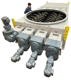
Whereas a plane-flow hopper section may require a feeder and stiffening of the flat surface to sustain the pressures exerted by the stored material, many site and process advantages can be gained from its selection. The key advantage — the ability to generate reliable flow of even strongly cohesive powders — demands that the feeder must extract progressively from the entire length of the hopper outlet slot. An integral design approach for both the feeder and the plane-flow hopper, based on the measured flow properties of the bulk material to be stored, ensures reliable flow along with the many benefits outlined in this article. For applications where the full hopper outlet width must be served to generate a full mass-flow pattern, a twin or even multi-screw feeder can be used, creating a larger flow area and saving even more headroom.3
References
- Bates. L. “Entrainment pattern of screw hopper dischargers,” ASME. Jrnl.Eng.Ind. May 1979, 295/302.
- Bates. L “Enhancing the performance of reversing feeders.” ICBMH 2013. Newcastle. Australia.
- McGee. E. “The Application of Multi Screwfeeders to Avoid Flow Problems - Sometimes one screw is not enough!” CHOPS 2022, Salerno, Italy.
Ajax Equipment
About the Author

Lyn Bates
Lyn Bates is chairman at Ajax Equipment.

