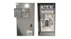
Process control panel design basics
In most modern processing plants, production equipment and systems incorporate at least some degree of automation. Sometimes it comes integrated with packaged equipment from original equipment manufacturer (OEM) vendors, and other times the controls are designed by engineering firms and systems integrators (SIs). Control panels are usually assembled in a shop dedicated to this work, and they are then factory-installed on OEM equipment or shipped to the field for “stick built” installations.
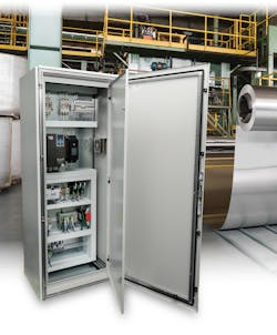
Designing the electrical, instrumentation and control (EIC) systems and panels supporting this widespread automation is a specialty. But end users of all types in a range of disciplines can benefit from understanding some of the fundamentals involved with designing and building a typical industrial control panel (Figure 1).
Requirements
While some types of instrumentation and industrial control components do not require a protective housing, it is more common for most EIC devices to be installed in control panels of some sort. Control panels protect these devices from local environmental conditions — heat, cold, moisture, contaminants — and they also protect workers from electrical voltages.
Typical industrial control panels fulfill many roles including some or all of the following:
- Providing a suitable environment for control devices.
- Keeping personnel safe and away from these devices.
- Performing power distribution and voltage conversion.
- Offering a centralized and maintainable location for programmable logic controllers (PLCs), input/output (I/O) modules, human-machine interfaces (HMIs) and related components.
- Supporting motor control devices like variable frequency drives (VFDs) and servo/motion controls.
- Housing communications and connectivity systems.
Specification documents, codes and regulations, and other less formal methods may drive requirements — but control panel designs must meet or exceed all these directives.
Utilities, signals and components
Some fundamentals for control panel design include electrical power needs, I/O and networking signals, and the components needed to perform these functions. Designers must be fully versed in these concepts, but end users should know enough to coordinate what is available at the site with new control panels, including these basic requirements:
- Incoming power circuit voltage and amps and how this affects the short circuit current rating (SCCR) requirements. Sometimes there will need to be multiple incoming power circuits, or perhaps a 480VAC 3-phase circuit that will be transformed and/or converted to other lower voltages within the control panel.
- Discrete I/O signal levels (120VAC or 24VDC sourced by the control panel, or dry contacts for interfacing with other systems).
- Analog I/O signal levels (4-20mA, 0-10VDC, or other).
- Networking media and protocols (such as serial, fieldbus, or Ethernet; and Modbus RTU, PROFIBUS, EtherNet/IP, etc.).
- Motor voltages and loads (FLA).
As components are selected, panel designers often find it helpful to create a block diagram showing the relationship of these devices. Once the components are selected, a rough approximation of the layout must be created so that the enclosure can be sized.
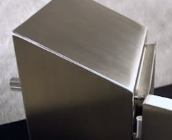
Once the size is known, it is necessary to choose an enclosure suitable for the environment. Painted carbon steel is standard and economical, but damp areas or locations with washdown requirements and exposure to chemicals may require stainless steel or fiberglass options. Food, beverage and pharmaceutical installations may require special sanitary enclosures that resist harboring contamination (Figure 2).
Of special importance for control panels is understanding the heating and cooling needs. Electrical and electronic components are designed to operate within a rated temperature range, and most of them generate heat, which can build up in an enclosure. Designers must consider all these factors, often with the help of sizing software, to determine what types of heating and cooling equipment will be needed to control the enclosure interior and help prevent any condensation.
Detailed drawings
Designers will next create a detailed drawing package for a control panel so a shop can assemble it for installation on equipment or in the field. End users may not need to understand every detail, but at the minimum they should confirm the control panel size and mounting arrangement is workable, and that the bill of materials appears to meet their needs. A typical drawing package should include:
- Cover page and drawing list.
- Bill of materials (BOM), a detailed list of makes/models/quantities indicating usage.
- Nameplate and tag schedule.
- Cable and/or wire lists, not always included, but helpful when cut-to-length cables and factory I/O wiring harnesses are used.
- Interior layouts with dimensions and wire management provisions shown.
- Main power distribution including incoming power, 3-line drawings for 3-phase AC power, all circuit breaker and fuse overcurrent protection, transformers, DC power supplies and grounding provisions.
- PLC power, data, and networking drawing(s); may also be called a system architecture diagram, and can include device addresses and communication settings.
- I/O module and signal drawings. Associated terminal strip drawings may be combined on these or separate.
- Specialty device drawings for VFDs, motion controllers, servos, safety controllers, instruments, etc.
- A block diagram indicating the basic relationship of major control panel components.
The preceding list may seem like a lot of detail, but it really is necessary to ensure a control panel performs as required and can be properly installed where it is needed. Panel designers consider many more detailed elements associated with power consumption, overcurrent protection, conductor sizing, cable routing, UL requirements and code compliance. However, a good drawing package describes the mechanical, electrical and pneumatic parameters in sufficient detail so end users can confirm the panel will meet their needs.
Testing
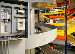
Thorough testing is necessary to ensure proper control panel assembly and functionality. As assembly is completed, the panel shop should provide proof that they have verified the parts used, the overall arrangement, proper tags and correct grounding/bonding. They should demonstrate that they have performed point-to-point wiring tests, progressively powered-on interior elements and checked basic circuit and I/O signals (Figure 3).
The most advanced tests will go beyond these basics to exercise PLC program functionality and demonstrate communications to VFDs, HMIs and other intelligent devices. This type of testing is more practical for control panels installed on OEM equipment, but many tests can be performed on control panels destined for stick-built installation.
Knowing process control panel basics benefits all
Industrial process control panels are more than just boxes stuffed with some electrical parts. Properly designing, assembling, testing and installing these control panels for safe and reliable operation — especially for operation in challenging field locations and using advanced automation devices — requires skilled personnel.
Many types of OEM machinery and processing systems are highly automated, and they include increasing numbers of sensors and intelligent devices. Considering this, end users of all types should familiarize themselves with control panel basics, and even some of the available products and technologies used in these panels, so they can work with panel designers to ensure their needs are met.
Chris Kregoski is a product engineer at AutomationDirect in Cumming, GA., on the Productivity PLC development and support team. He spent nearly a decade as the owner of Woodwest Controls, a small system integrator, servicing start-ups in malting, brewing, distilling and water treatment industries.
AutomationDirect
