Fit the pumping technology to the task
A regional light crude oil pipeline operator in the Western U.S. needed an economical, accurate way to measure crude inventory flow within its pumping stations. The pipeline operator transports partially processed crude to other lines or main terminals.
The oil and gas industry spends a lot of time and effort on good custody transfers. This is in part because product stewardship and ownership changes hands many times. Also, at each stage, multiple parties tend to own the product.
Accurate flow measurement is essential to cost-effective pipeline operation. Highly precise flow meters perform custody-transfer measurements for payment purposes, but intermediate process measurement points within pumping stations, for example, can be served with less expensive technology.
When oil moves any appreciable distance through a pipeline, pumping stations maintain product throughput rates. Flow rate and volume are monitored and metered to optimize pump operation as well as the resulting throughput to the terminal, refinery or custody transfer point end destination. The flow is also monitored as an early warning for leak detection.
Pipeline pumping stations are found in close proximity to equipment or facilities or where mountain ranges, long valleys or other relevant topographical features are located.
What was the case
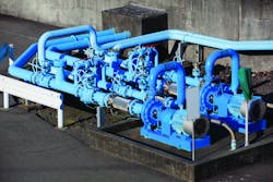
The regional pipeline company’s process engineers searched for a low cost but accurate flow measurement solution for internal inventory monitoring at its pump stations (see Image 1). No custody-transfer requirements applied, so a flow meter with an accuracy of ±0.5 percent was deemed suitable.
At the well site or soon after, the light crude in the pipeline already had passed through a heater/treater or main separator, which left it devoid of gases, water or other constituents that would disturb the specific gravity (SG) of the oil. In this region, the oil has an American Petroleum Institute gravity rating of 40 or above.
The light crude in the pipeline featured a viscosity of 2 to 8 centipoise. With pipeline diameters running from 6 to 8 inches, the liquid velocity varied between 1 to 16 feet/second. Flow meters are mounted to both the pump suction and discharge lines.
The engineering team reviewed several flow meter technologies, including Coriolis, differential pressure (dp), positive displacement and turbine. They also needed to look at installation requirements, maintenance and instrument life from a total life-cycle cost perspective.
In the crowded pumping station environment, the team wanted to avoid moving other pieces of equipment to accommodate the long upstream and downstream straight pipe requirements that many flow meter technologies require for accurate and repeatable measurement.
They were also concerned about flow meter post installation maintenance requirements representing additional cost. A maintenance intensive flow meter complicates a pipeline maintenance schedule with unnecessary tasks.
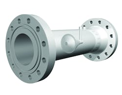
Image 2. Because long pipe runs are not needed for installation, the meter offers savings in applications within complex or crowded equipment layouts.
A self-conditioned flow
The V-cone flow meter (see Image 2) features a unique self-conditioning flow technology, offering low installation and maintenance cost and reliable measurement for light crude pipeline pumping station applications. Its no-moving parts design delivers safe, highly stable measurement, and the standard global agency approvals required for use worldwide promise several decades of proven service.
The meter offers significant cost savings in applications within complex or crowded equipment layouts. It makes use of a centrally located intrusion that redirects the flow to the outside of the pipe and conditions it by reshaping the velocity profile to all but eliminate the need for straight pipe runs.
The meter measures liquid, steam or gas in both clean and dirty fluids in line sizes from 0.5 to 120 inches. It is designed for mild to harsh operating environments and a wide variety of fluids in demanding operating environments. In addition, the meter operates well in potentially hazardous high temperature and high pressure environments.
The meter requires straight pipe runs of no more than 3 pipe diameters upstream or 1 pipe diameter downstream. This smaller footprint, requiring up to 70 percent less straight pipe without being affected by flow disturbing equipment up or downstream, is more compact than any other dp meters. Not only does the compact meter fit more easily into crowded equipment areas, but the installation cost is also significantly lower because it doesn’t require a long pipe straight run to operate with high accuracy and to provide repeatable measurement.
Principles of operation
The V-cone flow meter is a differential pressure meter. The principle of operation is based on Bernoulli’s theory of conservation of energy. In a closed system as the cross sectional area changes, the velocity must change as well. Placing the cone in the pipe reduces the cross sectional area, forcing fluid velocity to increase. As it does so, pressure drops. The measured pressure drop is used to determine the fluid flow rate by incorporation into a derivation of the Bernoulli equation.
As the fluid moves past the cone, very short vortices form that result in a low amplitude, high-frequency signal optimal for strong signal stability. The V-cone maintains ± 0.5 percent accuracy and ± 0.1 percent repeatability over a 10–to-1 turndown, and the cone conditions the fluid such that there is relatively low permanent head loss.
The meter’s low permanent head loss results from the shape of the cone itself, which minimizes the energy losses commonly caused by low flows, cavitation or erratic flows. Each V-cone flow meter is sized to meet desired application requirements and may be specifically designed to have high or low head loss. Regardless, the overall energy consumed by the meter is minimized because of its inherently efficient design characteristics.
The meter measures abrasive, dirty and particle-laden fluids over a wide range of Reynolds numbers without wear or clogging concerns. The result is a long operating life of 25 or more years with virtually no need for maintenance, which greatly reduces costs for users.
The turbulent vortices produced by the meter condition the liquid flow to be homogeneously distributed and stable. This turbulent flow actually protects the cone as well as the surrounding pipe. The turbulent flow forms a boundary layer against the pipe wall and cone, protecting it from particle impingement that causes deterioration or buildup on surfaces.
Normal surface deterioration in flow meters, piping and other equipment occurs as a result of fluid shear stress. Shear stress in laminar and unstable turbulent flows creates a problematic solid boundary layer in direct contact with the walls of the pipe. The meter’s stable turbulent flow helps rid of this shear stress and consequently the surface deterioration.
Additionally, because of the shape of the cone, little chance of cavitation occurs on the backside of the cone to erode the surface. No regular maintenance or recalibration is needed after installation.
Installed in varied applications
With its self-conditioning dp sensing technology, the V-cone flow meter is now installed in many oil production, refining and pipeline applications around the world.
For several decades, engineers in the oil industry have relied on the V-cone flow meter for accuracy in the toughest applications. Engineers recognize its benefits for applications held by the traditional dp technologies, such as Venturi tubes and orifice plates as well as turbine and positive displacement.
The V-cone meter’s no-moving-parts design all but eliminates the need to shut down production for calibrations, inspections or regular primary element replacement needed for an orifice plate.
Nick Voss is general manager with McCrometer, which develops precision flow meters for liquid, steam and gas measurement industry applications for its worldwide customers.


