Energy efficiency with compressed air
Knowing a plant’s compressed air system and selecting the most suitable type of air compressor and proper air treatment equipment for an application can be a challenging task considering the many different air compressors and air treatment equipment available on the market. Compressed air is used in many different manufacturing and process applications. A few are:
Pneumatic hand toolsThe first step to compressed air system design is a comprehensive evaluation of the expected air demand – including the total required volume per minute, measured in standard cubic feet per minute (scfm), and the highest required pressure, measured in psig. This is followed by applying a usage factor to determine the average air consumption. The peak consumption is be the sum of all the pneumatic equipment volume requirements. However, many pneumatic equipment air demands are not continuous, and therefore, the correct usage factor must be applied to each piece of equipment to avoid oversizing the system.
On the other hand, undersizing the system by considering only the average air demand may cause the system pressure to fall below the minimum operating pressure for the application, and this needs to be avoided as well. Once the average and peak air demands are determined, the system’s cubic feet per minute (cfm) range will need to be calculated to select the appropriate air compressor type, compressor controls and amount of necessary storage to satisfy the peak and intermittent air demands.
Air compressor types
The two major classes of air compressors are positive displacement and dynamic. The positive displacement class is subdivided into reciprocating (piston), rotary screw and rotary sliding vane compressors. These range in size from fractional horsepower (hp) to several hundred hp.
Reciprocating and rotary screw compressors are available in single-stage and two-stage options and oil-lubricated and oil-free options. Dynamic air compressors are centrifugal and axial and range from several hundred to several thousand hp. This article focuses on positive displacement compressors.
Reciprocating
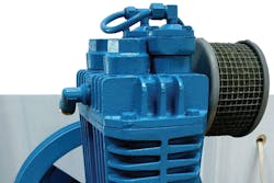
Reciprocating compressors have a piston or multiple pistons connected to a crankshaft with a connecting rod. As the crankshaft rotates, the piston reduces the volume of air in the cylinder, compressing it into a higher pressure. This type of compressor is relatively small, simple and typically available in 25 hp and below. Reciprocating compressors may be single stage or two stage, have a wide range of available discharge pressures, and are used with applications in which the air demand is predominantly intermittent.
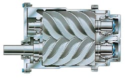
Cutaway view of a rotary screw compressor (air end).
Rotary screw
The rotary screw compressor has become the dominant compressor type for many process and manufacturing applications that require a continuous flow of compressed air. This type utilizes two intermeshing, helical rotors that compress the trapped air as it travels from the suction, or inlet, port to the discharge port. An oil-flooded rotary screw compressor injects lubricant into the compression chamber to perform the following:
- Lubricate the rotors and bearings
- Act as a seal between the meshing rotors
- Remove the heat of compression
This design has fewer moving parts when compared to a reciprocating compressor, provides a pulsation-free supply of compressed air and is designed to operate 24 hours per day, seven days per week.
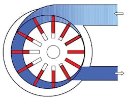
View of a sliding vane compressor
Rotary sliding vane
The basic design of a rotary sliding vane compressor consists of an eccentrically supported circular rotor housed in a cylindrical stator. The rotor has slots with vanes, or blades, that slide out under centrifugal force to contact the stator. As air enters the chamber, it is trapped between the blades and compressed as the chamber volume reduces in size near the discharge port. Vane compressors are similar to rotary screw compressors. They are available from 5 to 200 hp and are rated for discharge pressures up to 125 psig.
Compressor controls
Selecting the compressor type and what controls will be included is critical to system performance and efficiency. Reciprocating compressors are typically start-stop controlled with a pressure switch, and some manufacturers offer load and unload options. Rotary screw type compressors are available with four control types: load/unload, modulation, variable speed (VS) or variable displacement (offered by some manufacturers).
Load/unload controls use a pressure switch to unload the compressor when the pressure rises above the setpoint and loads back up when the pressure falls below the setpoint. When the compressor is in the unloaded state, it consumes energy, typically 20 to 50 percent of the rated hp, but the inlet valve is closed, and air is not being compressed.
Modulation control varies the position of the inlet valve, typically down to 30 percent open, which limits the amount of air compressed, preventing the pressure from increasing to the unload setpoint. Inlet valve modulation control is inefficient. At 60 percent capacity, the compressor will consume 85 percent of the required power.
VS compressors use an alternating-current inverter to vary the frequency and speed of the compressor. This, in turn, adjusts the compressed air output. A variable displacement compressor, also referred to as a spiral turn or lift valve, shortens the effective length of the compression chamber while the compression ratio remains relatively constant. This type of control has advantages when compared to VS:
- Better efficiency above 80 percent capacity
- No drive efficiency losses (3 to 4 percent)
- Operates at 100 percent capacity (VS compressors are intended to operate below 90 percent capacity.)
- Installable in harsh environments that would cause a VFD to fail prematurely
Selecting a compressor control suited to the application is as important as – if not more important than – the type of compressor chosen. Knowing the fluctuation range of the air demand will determine the best type of control system to select.
Air receivers
Every compressed air system must have adequate storage to maximize system efficiency. The physical storage volume, including the pipes and receivers, determines the rate and size of the pressure change in the system as the demand for air changes. It also determines the efficiency of the air compressors when their controls are loaded/unloaded. The larger the storage volume relative to the size of the individual compressor, the more efficient the compressor is in terms of scfm/hp. This is because the compressor can reach its unloaded power and remain in that condition for longer periods of time as the system pressure decays to the reload setpoint.
The two main types of storage are primary and secondary. The primary receivers are within the compressor area and are commonly referred to as wet and dry tanks. An adequately sized wet storage tank, installed immediately downstream of the air compressor, shields the compressor control system from rapid pressure fluctuations from the demand side. A dry storage tank, installed downstream of the air treatment equipment, uses dry air as stored energy during periods of peak and high air demands.
The larger the storage capacity, the more stable the system pressure is, and this is the key to operating a compressor system efficiently. Secondary receivers are located at the point of use and used when the pneumatic equipment requires a large volume of air for a short period. Installing a properly sized secondary receiver prevents sudden system pressure drops.
Air treatment – air dryers
An air compressor compresses ambient air and everything contained in the ambient air including particles and moisture vapor. The compressed air leaving an air compressor is saturated with moisture and will damage pneumatic equipment if the moisture is not removed. The three major classes of air dryers are refrigerated, desiccant and membrane.
Refrigerated dryers
Refrigerated air dryers use heat exchangers and a refrigeration system to cool the stream of compressed air to a 35oF to 38oF pressure dew point. At this temperature, the moisture vapor condenses into a liquid and is purged with an automatic drain.
The compressed air is then reheated before leaving the air dryer to maintain the air temperature at ambient temperature, which prevents the air pipes from sweating. Refrigerated air dryers are available in non-cycling or cycling options.
A non-cycling air dryer refrigeration system operates continuously and uses the hot gas bypass valve to prevent internal freezing if the air flow is very low. A cycling air dryer’s temperature controls turn the refrigeration system off during periods of low air demand to save on energy. Refrigerated air dryers are commonly found in most applications because of their low initial cost and reduced maintenance requirements.
Desiccant dryers
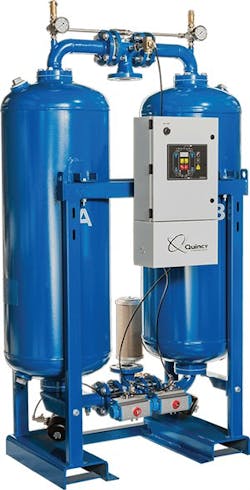
Desiccant air dryers are selected if an application requires the pressure dew point to be lower than 35oF. This type uses a desiccant medium to absorb moisture from the air stream. Generally, desiccant dryers are constructed with twin towers with each tower containing the desiccant medium. The desiccant medium has a finite capacity for absorbing moisture before it must be dried out, or regenerated. To do this, the desiccant tower must be depressurized and the accumulated water driven off using purge air, heat or both.
The twin-tower design allows one tower to absorb the moisture as the other tower dries. Unlike refrigerated air dryers, desiccant air dryers require a small amount of compressed air – typically from 3 to 20 percent depending on the type – to purge the moisture and repressurize the tower.
Membrane dryers
Membrane technology is commonly used for gas separation. Membrane dryers for compressed air use a membrane structure that allows water vapor to pass through the membrane pores faster than the air, therefore suppressing the pressure dew point. Similar to desiccant dryers, membrane dryers consume compressed air to purge the moisture.
Air treatment – filtration
Desiccant dryer
Each compressed air system application has a different air quality requirement. A standard air quality classification has been developed, International Organization for Standardization (ISO) 8573.1, which defines the allowable amount of solids, moisture and oil content remaining in the air stream. Although pneumatic tools can tolerate a lower air quality, critical instrumentation and many pneumatic controls require extremely clean and dry air.
Selecting the correct filters for each application is necessary to prevent damage to the instruments and/or tools. A typical arrangement would include a 1-micron-rated coalescing filter located upstream of the air dryer to remove the bulk liquid and a 0.01-micron coalescing filter located downstream of the air dryer. An activated carbon filter rated at 0.003 parts per million (ppm) further purifies the air stream for critical applications.
Distribution (piping) system
Transmitting the sufficient amount of compressed air from the compressor to the final points of use at the required pressure is necessary for efficient system operation. Considerations include the type of piping material, the air-volume flow rate, the air velocity and limiting the pressure drop caused by friction.
Selecting the appropriate piping material is based on the application requirements and the environment in which it will be installed. Copper; extruded aluminum; and carbon, galvanized, or stainless steel piping are suitable choices for compressed air systems. To ensure safety, a system designer must always consider the pressure rating of the selected piping material. Copper, stainless steel and aluminum piping have a smooth bore and are preferred choices because of their low pressure losses resulting from friction.
Air pressure drop charts are available to compare the different pipe materials and pipe sizes, but the velocity with which the air will travel is equally important. A properly designed distribution system limits the velocity to around 20 feet per second (fps) and should never exceed 30 fps. A slow-moving air stream ensures a low pressure drop and stable air pressure.
Compressed air system equipment selection example
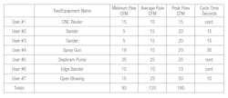
The article has briefly described the different types of air compressors, compressor controls, storage, dryers, filtration and the distribution system. Now it is time to use a manufacturing facility example to design and select the appropriate system components. Table 1 shows an air-demand worksheet for the pneumatic equipment planned for use in a facility.
Table 1. Air demand worksheet
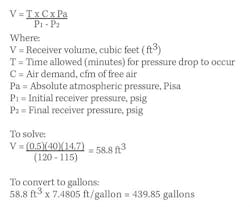
Table 1 shows that the peak flow is 160 cfm, but the average flow is 120 cfm. The 40 cfm difference – based on the largest cycle time of 30 seconds and considering P1 is 120 psig (inlet receiver pressure) and an acceptable 5-psi drop in pressure – can be satisfied with storage as follows:
For this example, a suggested standard air receiver size of 400 gallons is appropriate.
To select an appropriate air compressor to satisfy 120-cfm air demands, a reciprocating compressor is ruled out because the air demand will be continuous, and 120 cfm exceeds the rated capacity of a typical 25-hp unit. Moving to rotary screw compressors, a 30-hp Quincy compressor model QSI-140 with load/unload controls rated for 130 cfm at 125 psig was selected. The option of a 120-gallon, tank-mounted compressor was also selected to provide additional control storage.
When selecting a rotary screw type compressor, the key features of a premium quality machine are:
- The size of the air end
- How the drive motor is coupled to the air end
- The air end operating speed
- The life expectancy
Less expensive compressors will be belt driven, use small, gear-driven air ends, and operate at a very high rpm. Premium compressors will be direct drive, have large air ends and operate at low speeds.
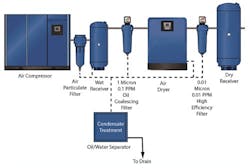
After the air compressor was selected, a suitable air dryer and filtration system became the priority. The pneumatic tools and equipment require an ISO 8573.1 classification of 1 – 4 – 1, which provides a solids rating of 0.01 micron, a dryness of 38oF pressure dew point, and 0.01 ppm of remaining oil content. A 150-cfm-rated refrigerated air dryer with pre- and post-filtration was selected. Considering this sized air dryer will require only 1 kilowatt, a non-cycling type air dryer was chosen. The completed equipment selection and how the components were installed is shown in Figure 1.
Figure 1. Selected equipment installation map
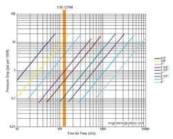
When the expected air flow has been established, the distribution system can be designed. The facility is 14,000 square feet, while the production area is 8,000 square feet and approximately 150 feet away from the compressor room. Figure 2 shows a pressure drop chart for schedule 40 pipe and an applied pressure of 100 psig, with a pressure drop per 100 feet of straight pipe.
Figure 2. Pressure drop chart; applied pressure 100 psig
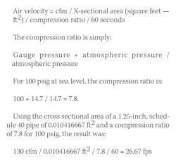
Figure 2 shows that 130 cfm of air flowing through 100 feet of 1.25-inch pipe will have a 1 psig drop. Assuming 150 feet, the total pressure drop was 1.5 psig, which might seem acceptable. However, the velocity should also be calculated to make sure it is approximately 20 fps and always less than 30 fps. The simple formula for calculating velocity is:
Calculating for a 1.5-inch pipe, the result is 19.6 fps. Referring to Figure 2, a 1.5-inch pipe shows a 0.5-psig pressure drop for 100 feet and 0.75 psig total for 150 feet. The difference in cost between 1.25-inch and 1.5-inch pipe is small, and for this distribution system, a 1.5-inch pipe was selected.
Conclusion
The example represents a basic process for selecting the components of a compressed air system and the steps end users should take. Every compressed air system is as unique as the address in which it is installed and how the manufacturing process consumes air. Compressed air is not free and is considered a fourth utility. Properly designing the air compressed system will ensure energy efficiency and provide stable pressure to the process.
Dr. Khalil Kairouz (corresponding author) is an associate vice president at Carollo Engineers, a consulting firm that specializes exclusively in water and wastewater treatment systems, located in Costa Mesa, California. He has a doctorate in mechanical engineering and taught at Loyola Marymount University and California State University in the Mechanical Engineering Department. He may be contacted at [email protected].
Daniel Jazdzyk is a compressed air and vacccum system engineer and has been designing compressed air systems for 20 years. He has a balchlor’s degree in mechanical engineering from Worchester Polytechnic and completed the Compressed Air Challenge — Advanced Management of Compressed Air Systems. He currenty works for Quincy Compressor located in Santa Ana, California. He may be contacted at [email protected].
Safaa Al Musawi is the CEO of Gilgamis Group, an international engineering and construction firm located in Turkey. He has a master’s degree in elecrtrical engineering and is currently pursuing his doctorate in electrical engineering at the University of Belgrade, Serbia. He has designed, installed and started up many types of compressed air systems worldwide. He may be reached at [email protected].
