Common pitfalls in designing emergency pressure relief systems
An emergency pressure relief system (EPRS) is the most frequently employed layer of protection option for overpressure safeguarding in the chemical, pharmaceutical and allied industries. It protects reactors, storage tanks, columns, boilers, dryers and other processing equipment. When designed, operated and maintained properly, an EPRS can be cost-effective and reliable, ensuring staff and environmental safety. However, incidents continue to occur that reveal common failures along the system’s life cycle.
The right design
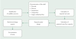
State-of-the-art design methods for relief systems are based upon the work of DIERS (Design Institute for Emergency Relief Systems) and subsequent supporting research.1 The principal steps in designing an emergency relief system follow an established flow chart as shown in Figure 1.
Scenario identification
An emergency relief system must be designed for the situation that requires the largest relief capacity among all potential relief scenarios, making scenario identification the first step in EPRS design. However, often there is either no scenario identification whatsoever, or some significant scenario is missing.
Figure 1. EPRS design steps
Missing runaway reaction scenarios is typical of plants designed and built referring only to general standards such as API 520 and 5212 or ISO 4126,3 or even internal standards and criteria, which rarely include consideration of runaway chemical reactions or thermal decomposition. Plant owners also sometimes fail to share essential chemical reaction information. A vessel’s relief device may be insufficient because it has been dimensioned for a substance or scenario other than the one for which the vessel is intended. Moreover, the use of equipment can change, resulting in the EPRS being inadequate for the new situation.
The runaway reaction incident at T2 Laboratories on Dec. 19, 2007 provides an example where a relief device (a rupture disc) existed, opened when the set pressure was reached and yet failed to relieve the pressure because it had been improperly dimensioned. The subsequent explosion killed four people, injured 32 and caused significant loss of property, including the total destruction of the plant.⁴
Clearly, an EPRS is a critical safety element and must be designed taking into account the risk tolerability criteria of the owner and a process hazard analysis that includes an exhaustive list of potential overpressure scenarios, their relief conditions and associated risks.
Calculation of vent area
Once the scenarios have been identified and characterized, the vent area needs to be calculated. The main mistakes here are: insufficient chemical reaction data to support calculation; widely different flow rates safeguarded by the same relief device; and unrealistic calculated conditions.
Even for simple fire relief calculations, the wrong formula can result in vastly undersized relief conditions. If, for example, calculations do not reflect that equipment is enclosed in a concrete vault, the relief system will be severely undersized.
In relief scenarios associated with runaway reactions or thermal decomposition, it is critical to use sound data that may require a number of laboratory tests to collect. While this can be costly, using the wrong data can lead to incorrect sizing and is equivalent to not having identified the scenario.
Multipurpose reactors can be particularly challenging due to the wide range of products made in such vessels. One undersized relief system was the result of assuming that the scenario with the highest reaction energy would be the worst case, while in reality the worst case had a lower reaction energy, but no mass transfer limitations.
The chattering phenomenon
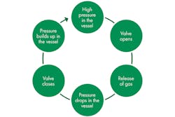
When a system with a wide range of flow rates has only one safety valve, it may lead to the so-called "chattering" phenomenon. This occurs when the high-capacity valve designed for large scenarios opens as a result of a scenario requiring smaller capacity. It relieves the pressure very quickly and closes, but the pressure builds up again, causing the repeated opening and immediate closing of the valve. The cycle,
pictured in Figure 2, can repeat at a very fast rate, potentially damaging the valve.
Figure 2. Chattering cycle
A system safeguarded by a rupture disc resolves the chattering issue. Another possible solution is the application of special pilot-operated relief valves. A third option is installing twin relief devices with staged set pressures: a smaller relief valve with a lower set pressure for the "minor" cases and a parallel bursting disc for the "credible worst-case scenario" with a higher rupture pressure. Often, however, there is insufficient margin between the normal operating pressure and the vessel design pressure to accommodate this approach.
Upstream and downstream systems: Disposal
Unsuitable pipework upstream or downstream from the relief device or careless disposal can render useless the best-designed EPRS.
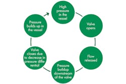
Pressure relief valves and rupture discs operate under differential pressure between upstream and downstream side.⁵ If the opening of a relief device causes pressure buildup in the collectors downstream, it may prevent other devices from opening correctly in scenarios affecting adjacent vessels.
Figure 3. Chattering caused by repeating cycles
Even if the relief device opens, the head losses in the piping can be so large that the pressure differential between the protected vessel and the final disposal point precludes the flow rate required, rendering the system ineffective. If excessive pressure buildup downstream of a safety valve still allows the required flow rate, it can cause chattering and the resultant decreased capacity and rapid destruction of the valve. In this case, chattering is caused by repeated cycles as shown in Figure 3.
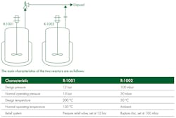
It is inadvisable to connect relief devices with very different set pressures to a common collector. If the high-pressure device opens, it can create sufficient overpressure in the collector to prevent opening of the low-pressure relief devices. Even worse, if the low-pressure devices are rupture discs, they could open backward, pressurizing the low-pressure section of a plant. Consider the system shown in Figure 4.
If the safety valve that protects R-1001 opens, the pressure in the collector will likely be higher than 100 millibar (mbar), the set pressure of the rupture disc protecting R-1002. The disc will then break, allowing backflow of the substances released from R-1001 into R-1002, leading to overpressure and ultimately to a catastrophic rupture.
Two valid solutions to this case are:
- Collect and dispose of high and low-pressure systems separately (preferred method).
- Collect both systems into an intermediate catch tank sufficiently large and well-vented, so that if the safety valve in R-1001 opens, the pressure buildup in the catch tank is still small enough to allow normal operation of the rupture disc of R-1002. This type of solution usually leads to enormous catch tanks and requires an extremely accurate analysis of relieving scenarios in both vessels to guarantee correct sizing.
Figure 4. Reactor system
When incompatible chemicals are collected in the piping of an EPRS and two relief devices open simultaneously, disaster can ensue. While the simultaneous triggering of two devices is exceedingly rare, if the vessels they safeguard are sufficiently close or share some utilities, there might be common cause failures. And though simultaneous venting may be unusual, sequential venting of one vessel after another occurs more frequently. For example, if: A fire engulfs both vessels; A failure in cooling water causes a runaway reaction in one reactor and the loss of cooling capacity in the condenser of a nearby distillation column; A blackout at the plant causes failure of all the aerocondensers.
Plants with multipurpose reactors where many different processes run simultaneously are especially prone to this type of problem.
It is not advisable to vent hazardous gases, liquids or vapors directly into the atmosphere. Liquids need to be collected separately from gases, usually with a properly dimensioned knock-out drum. When liquid is expected in the release, the piping should be carefully designed to avoid pockets in low points that could lead to head losses, exothermal reactions, thermal decomposition, polymerization or freezing of liquid. Exothermal reactions or thermal decomposition damage pipes and release hazardous materials, while polymerization or freezing plugs piping, which may go undetected until overpressure in a vessel cannot be relieved because the venting pipe is blocked downstream.
A flare can safely dispose of flammable gases and vapors. If a flare is not available, and assuming that the gases are only flammable and environmental regulations permit, they can be vented at sufficient height so as not reach ignition sources. When the gases or vapors are toxic or corrosive, they need to be treated in a flare or scrubber or, regulations permitting, be vented at sufficient height to be dispersed without causing harm. At present, regulatory bodies often request dispersion calculations to prove that ground-level concentrations are harmless.
These disposal requirements can give rise to mistakes that limit the effectiveness of the EPRS. The whole EPRS system, including piping, valves and disposal systems should be kept to a simple design to maximize reliability.
Documentation
EPRS documentation becomes critical when changes are made to a plant or process. Without documentation, nobody will be able to tell whether: The changes give rise to new relief scenarios; The existing relief scenarios and conditions are still valid; The risk associated with existing scenarios has increased; or the system has sufficient capacity and reliability to safeguard any new scenarios, and any changes in the existing scenarios.
If the process safety culture of the plant owner is sufficiently high, poor documentation will lead to a redesign of the system.
Installation
Faulty EPRS installation can be a source of error, so testing is key. However, pressure relief valves are difficult to test in situ, and rupture discs cannot be tested at all. A pre-startup safety review (PSSR) program is therefore essential. Failing to carry one out can seriously compromise the safety of the plant.
For instance, there was a reported case⁶ where a rupture disc was installed upside down because of a misreading of the drawings. Nobody checked the installation. As a consequence, a 90 m3 tank weighing 4 tons lifted off like a rocket, rose to about 30 m and landed on a van. Fortunately, there were no injuries. Numerous other disasters could have been prevented by a thorough investigation, illustrating the importance of PSSR for every startup, not just when equipment is new.
Maintenance and inspection
Relying on the EPRS to work without inspections is unwise because equipment tends to deteriorate with age. Even a small leak in a rupture disk or safety valve can have catastrophic consequences.⁷
The only way to maintain a system’s reliability is to inspect its components periodically. Risk-based inspection and risk-based maintenance, as supported by recommended practices such as ANSI/API RP 580⁸ and API RP 581⁹, give detailed procedures to determine maintenance and inspection frequencies, but these should be reviewed according to site experience. The higher the risk, the more frequently inspection is required. In addition, some equipment
deteriorates faster than others, and this, too, influences inspection frequency.
Management of change
By introducing changes into a process, any one of the mistakes previously described becomes more likely, even if the EPRS is perfectly designed. Change management processes should, therefore, include a review of the entire EPRS, not only the valves or discs. For instance, after a capacity expansion in a continuous process manufacturing plant, inspection revealed that the flare was insufficient to cope with the largest release scenario. A high integrity pressure protection system (HIPPS) was designed for this specific case.
Conclusions
A well-designed, operated and maintained EPRS is a cost-efficient and highly reliable safeguard against overpressure in process plants. However, a number of common mistakes can render the system inefficient or insufficiently reliable. As the EPRS is typically the last layer of protection before a catastrophic failure and release of hazardous materials and energy, every phase in the life cycle of the system requires special care, including auxiliary equipment such as pipes and disposal systems.
References
- Emergency Relief System Design Using DIERS Technology. Design Institute for Emergency Relief Systems, 1992.
- Standard 520. Sizing, Selection, and Installation of Pressure-Relieving Devices. Part I – Sizing and Selection. American Petroleum Institute, 2014.
- ISO 4126. Safety devices for protection against excessive pressure. Parts 1 to 10. Safety valves. International Organization for Standardization, 2003–2016.
- Investigation Report 2008-3-I-FL.T2 Laboratories, Inc. Runaway reaction (Four Killed, 32 Injured). U.S. Chemical Safety and Hazard Investigation Board, September 2009.
- Some pressure relief valves can compensate downstream overpressure, within a limited range.
- Hedlund, FH et al., Large Steel Tank Fails and Rockets to Height of 30 meters – Rupture Disc Installed Incorrectly, Safety and Health at Work, 2016.
- The Report of the BP U.S. Refineries Independent Safety Review Panel
- ANSI/API RP 580 – Risk Based Inspection (RBI). American Petroleum Institute, 2016.
- API RP 581 – Risk Based Inspection Technology. American Petroleum Institute, 2016.
Keith Middle is a Principal Process Safety Specialist at DEKRA Process Safety. His expertise covers process hazard identification, assessment of chemical reaction hazards and the provision of practical engineering solutions. Particular specialties include HAZOP leadership, SIL determination to IEC 61508/11, the design of emergency relief systems using DIERS techniques, and the specification of vent treatment systems. He may be reached at [email protected].
John Wincek has more than 25 years of industry experience, including 17 years dedicated to managing all aspects of process safety in the specialty chemical manufacturing industry. He has led process hazard studies, conducted layer of protection analyses and chemical reaction safety assessments for facilities around the globe. He may be reached at [email protected].
Pieter de Kort has more than 25 years of experience in the process industry gained through various positions in process safety for large chemical companies. His main areas of expertise are process safety management, incident investigation, due diligence studies, chemical reaction hazards, HSE auditing and process hazard analysis (PHR, HAZOP, What-If) facilitation. He may be reached at [email protected].
Dr. Arturo Trujillo is Global Director of Process Safety Consulting. His main areas of expertise are diverse types of process hazard analysis (HAZOP, What-if, HAZID), consequence analysis and quantitative risk analysis. He may be reached at [email protected].
