Better ways to use differential pressure for liquid level measurement
Using differential pressure as a technology to measure level in tanks and vessels is a common technique, but many users apply it in ways that decrease reading accuracy or create maintenance headaches. In this article, we’ll look at a few basic concepts of the technology and then analyze an example application to provide ideas for improving and troubleshooting new and existing installations.
Liquid residing in any type of vessel or tank develops pressure caused by its own weight, allowing pressure to be measured in inches of water column. If one were to drill into the side of a tank and insert a gauge calibrated to sense the proper range pressure and it indicated 120 inches, and if the tank is holding water and is open to the atmosphere, one can rightly conclude there is 10 feet of water above the gauge. The underlying principle is simple to understand but implementing it can get complicated quickly.
First, density is a factor. The specific gravity of the liquid has to be included in the calculation to turn pressure into depth. If the liquid and its characteristics are well understood, including the effects of temperature, the level measurement will have the same degree of precision as the pressure instrument.
Second, if the tank is not vented to atmosphere, the interior could be above or below atmospheric pressure. If the instrument measuring level is reading against atmosphere, the interior pressure of the system adds to the pressure of the liquid and can change the calculated level reading drastically because it is reading the pressure of the liquid plus the system pressure. Under these conditions, the simple pressure gauge has to be replaced with a differential pressure (DP) gauge with the high side connected to the liquid contents and the low side to the head space above the liquid. With this approach, the reading self-compensates and provides a correct indication of liquid level.
These are basic enough concepts. Usually a company understands its process and products sufficiently to overcome the density question, but implementing DP measuring techniques can be more challenging.
Basic implementations
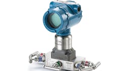
The simplest implementation for the two connections of the DP reading using a digital transmitter (Figure 1) is to put a direct impulse line to the high side from the liquid tap, and then run a line from a tap at the top of the tank to the low side. The first connection is wet and the second is dry. The problem with this approach is that the impulse lines and the transmitter itself are now part of the process containment. A loose tube fitting or breach of any kind in the lines or transmitter is a loss of containment. If the process is benign and the operating temperatures and pressures are not excessive, this might be perfectly adequate.
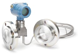
Where conditions are more critical, the process connections on the tank typically use a flanged spud and the transmitter connection uses a diaphragm (Figure 2), which keeps the process medium inside because the pressure is transmitted via an incompressible fill fluid inside the impulse lines on both sides. While this is very effective at protecting the process and the transmitter, once the lines containing fluid come into the picture, they introduce several side effects that can affect reading accuracy.
Problems with impulse lines
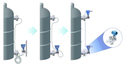
Depending on the height of the tank, the headspace tap at the top can be a long distance from the main transmitter. Under these conditions, the weight of the fill fluid becomes a factor as it creates its own pressure, distorting the headspace measurement. Naturally there are mechanisms to mitigate this problem (Figure 3, a and b), which generally involve ways to compensate for the impulse lines.
Fluid-filled impulse lines also present a variety of difficulties related to temperature differentials. If the process is hot, the fill fluid needs to be capable of withstanding the high temperature without vaporizing. This is usually not a problem given the high temperature tolerance of certain fluids, but these fluids tend to become viscous at typical ambient temperatures. Consequently, some impulse lines need heat tracing in cold environments to avoid the fluid becoming too cold and viscous to transmit data reliably once removed from the process heat.
Simplifying installations while preserving reliable process containment often begins with getting rid of the long impulse line from the upper headspace tap. One highly effective approach uses a second pressure transmitter mounted at the top of the tank (Figure 3, c) as an electronic remote sensor (ERS) to measure headspace pressure and send the data electronically to the main DP transmitter at the bottom. This eliminates the long impulse line and all its problems.
Using two transmitters in tandem is not a new idea, but getting such a setup to provide the degree of accuracy sufficient for effective process control or inventory management requires modern high-precision transmitters. If a process is pressurized at 100 psi and the tank has 10 feet of water, the upper and lower transmitters will read 100.00 psi and 104.34 psi, respectively. Both readings must be within a tight tolerance band to provide the level measurement, and this is only possible with matched transmitters providing high repeatability. With tolerance of ±1%, the level reading could indicate anything from 91 to 149 inches, hence the need for high precision. This application calls for tolerance ranges with fractions of percentages, which fortunately is possible with modern high-end transmitters.
Learning from a difficult application
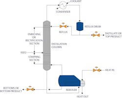
Much can be learned from difficult applications and applied to less complex situations. Here is a case in point: measuring level in a distillation tower using DP. A typical distillation tower (Figure 4) receives a mixture of heated liquids which turn into vapors that can be separated using their differing boiling points. Most towers have trays arranged at specific levels where specific vapors will condense in a fairly pure form, allowing the components to separate into their respective streams.
Normally the inlet is near the midpoint of the tower, and through downward flow of liquids and upward flow of vapors, the liquids separate into the lightest/lowest boiling components at the top and the heaviest/highest boiling components at the bottom. The liquid level at the bottom of the tower is the most critical measurement. When the process runs correctly, the liquid level will remain within a narrow range. It has to be high enough for the re-boiler to do its job but below the lowest trays. Major industrial disasters, such as the accident at the BP Texas City plant in 2005, have resulted from towers filling with liquid because malfunctioning level measurements caused operators to pump in too much liquid (U.S. Chemical Safety Hazard and Investigation Board, Mar. 20, 2007 https://www.csb.gov/bp-america-refinery-explosion/)1.
Distillation towers present multiple challenges for measuring level:
- There are too many internal obstructions for any top-down technology to work.
- The interior is pressurized, and this pressure varies with throughput.
- There can easily be 100 feet or more between the top and bottom measurement points.
- The fluid is usually hot with temperature ranges from 200-600° F.
Let’s look at these factors individually and see how to solve the challenges.
1. With all the trays and other internal structures, the only practical approach for measuring level is DP since no top-down technology can do the job. Moreover, even if there were no obstructions, the distances often involved would be beyond the range capabilities of most radar transmitters.
2. Towers are sealed and invariably pressurized, which means the head-space measurement has to be part of the level calculation. Some have free internal flows with consistent pressure across the entire height, while the trays and liquid flows of others create internal pressure profiles that can complicate the level measurement. An ERS can help characterize such profiles to solve measurement challenges.
3. Tall towers create the problems with impulse lines discussed earlier, so this is an excellent situation where an ERS with two transmitters can avoid distance compensation and temperature gradient issues with fill-fluids. There will be no need for heat tracing or other maintenance-intensive approaches.
4. The one topic remaining is temperature. Distillation towers can be very hot, both at the top and bottom — frequently too hot for conventional transmitters mounted directly to spud. Users often try to solve the problem by installing an impulse line to create some protective distance, but this introduces all the operational and maintenance headaches related to impulse lines.
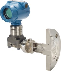
To address this issue, there are self-contained diaphragm and transmitter assemblies (Figure 5) that have internal fluid-filled sections designed to minimize heat transfer between the process and transmitter, while avoiding the usual drawbacks. These assemblies use two fluids: one selected to withstand the full process heat and a second suited for ambient conditions.
The high temperature fluid is contained in a capillary tube between the main diaphragm and a second internal diaphragm, and the tube transmits pressure to the second fluid, which contacts the actual measuring diaphragm. The assembly is fully sealed and protected to avoid any physical damage to the mechanism. This type of assembly increases the thermal range possible for the transmitter, providing greater application flexibility.
Solutions simplify complexity
DP can serve applications well whether the primary objective is inventory management, process control or improved safety. DP can provide a high degree of precision and repeatability but is still economical. If new technological
References
1. U.S. Chemical Safety Hazard and Investigation Board, Mar. 20, 2007 https://www.csb.gov/bp-america-refinery-explosion/
Nicole Meidl is a product manager for Emerson in Shakopee, Minnesota. She specializes in Rosemount DP level products, but in her five years with Emerson she has managed Rosemount pressure transmitters, multi-variable transmitters and electronic remote sensor systems. Nicole has a bachelor’s degree in mechanical engineering and is currently pursuing an Master’s in Business Administration from the University of St. Thomas in St. Paul.
