How to improve temperature measurement response times
The steak is sizzling on the grill, and the barbecue master stabs in a digital meat thermometer to check its progress. The numbers on the display jump quickly from 80 to 95 to 110 degrees but then begin to slow down, increasing by smaller and smaller increments. After a minute or so, the temperature comes to rest at 131. Done! The steak goes on the platter as rare perfection. This example of temperature measurement illustrates some of the same characteristics that create challenges for process and instrumentation engineers.
Of the four main process variables (flow, level, pressure and temperature), temperature is the only one where a sudden change cannot be recognized and measured relatively quickly. A rapid movement in one of the other three variables can be seen through the instrumentation in a few seconds, but a rise or fall in temperature can take a while to fully quantify. For most, this is simply a fact of life — we recognize the characteristic and live with it since temperature doesn’t usually change all that fast anyway. However, in some situations the lag can be a significant problem. Fortunately, there are ways to improve response time, which we’ll discuss, but let’s first look at the causes of temperature measurement lags.
Why the lag?
The two main approaches to measuring temperature electronically are: resistance (resistance temperature detector [RTD] and thermistor) and voltage (thermocouple). In both situations the value indicated is the temperature of the sensor, which may or may not be exactly equal to the process media temperature. Getting an accurate measurement depends on bringing the sensing element to the same temperature as the process media. While this may sound like a simple problem to solve, in actual application it can be difficult.
Measuring optically using infrared is effectively instantaneous; however, this approach is subject to severe limitations when measuring gas or liquid temperature — the most common process media. Infrared may be useful for many things, but for most process temperature measurement applications, it has limited applicability so we will ignore it for purposes of this discussion. We will also describe applications in terms of a process moving from cool to hot, but the opposite can also be the case.
A sensing element is usually encased in a stainless steel sheath, typically about 0.25 inches (6 millimeters) in diameter. The length varies, but the diameter is usually this or smaller. This protective sheath is particularly important for RTDs because the sensing element is delicate. Thermocouples may be provided as naked wires without a sheath, but this is more an exception than a rule.
Heat from the process has to be transferred through the sheath and whatever insulation may be packed inside the sheath to reach the sensor, hence the delay. Stainless steel in its various forms is one of the most versatile alloys ever invented, but it has one major drawback: it is a poor conductor of heat (see Table 1). Nonetheless, its myriad advantages outweigh this shortcoming, and it is almost universal for temperature sensor sheaths.
The thermal conductivity value of a sheath is determined by the alloy, but the actual length of time to reach the sensor is influenced by its size and thickness. The more material, the more time it takes for the heat to migrate through the sheath wall to the sensor. As noted, inside the sheath, the sensor is usually enclosed in insulating material to protect it physically and electrically. The heat coming through the sheath wall also has to heat the insulation before it reaches the sensor itself.
The rate of heat transfer for a given sensor and sheath assembly is fixed due to its construction. Other aspects of the application are variable, such as the heat transfer ability of the fluid and the temperature differential. The sensor assembly inserted into 150°F air will warm up more slowly than if inserted into liquid at the same temperature since liquid transfers heat more effectively. Additionally, fluid movement helps speed up the transfer since it can reduce the formation of a boundary layer of cooler fluid.
Temperature difference is also a major factor since the greater the difference, the faster the transfer of heat. As our barbecue master observed, when the measured and actual temperature get closer to equilibrium, the rate of change slows.
Getting through another layer
The discussion so far has ignored one additional major complication: a sensor is not normally inserted into the process by itself. There are some applications where it happens in the real world, but more often a sheathed sensor is inserted into a thermowell, which then is inserted into the process. The thermowell is part of the process containment and allows the sensor to be removed if necessary without shutting down the process.
This has obvious advantages, but it adds another layer of metal, often stainless steel, through which the heat must migrate to reach the sensor. Moreover, there is a gap between the inside of the thermowell and the sensor sheath, reducing direct physical contact between the sensor and the process media. The inside of the thermowell in effect becomes an oven, and much of the heat transfer has to be via air rather than direct metal-to-metal contact. This effect is exaggerated if the sensor is not fully inserted into the thermowell as there is more distance between the metal surfaces, increasing the distance through which heat must be transferred by air.
Fluid flow and fatigue failure
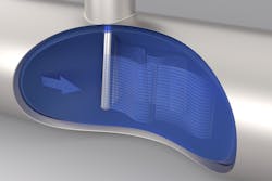
When a thermowell is inserted into a moving fluid stream, wake-shedding effects cause the thermowell and the sensor inside it to vibrate (see Figure 1). If the vibration is severe enough, it can cause metal fatigue over time that results in thermowell failure (see Figure 2). To withstand the vibration and extend operating life, thermowells with thick walls are often specified. Wall thicknesses of 0.5 inches (12 millimeters) and even greater are common.
Figure 2. If subjected to enough vibration, a thermowell can simply break off, causing a loss of process containment.
Obviously, these greater wall thicknesses increase heat transfer time, but apart from slowing response time, they can also affect the accuracy with which temperature can be measured. If enough of the mass of the thermowell is outside the process, it can serve as a heat sink, allowing heat to flow out of the process where it is dissipated by a flange and other parts outside of the process media stream. The inside of the thermowell never reaches the full process temperature, and therefore the reading sent by the sensor is consistently low.
In this context, the poor conductivity of stainless steel is actually an advantage. Naturally, the extent of the problem depends on the length of the thermowell, the overall amount of metal involved and the
difference between the process and ambient temperatures. External pipe insulation can mitigate the problem if it isn’t practical to change the thermowell profile.
Temperature loops and response time
So, what are we to make of this problem? Situations where it is only necessary to monitor temperature are usually manageable — but situations where temperature is used for control are more difficult. Generally, temperature is a slow-moving variable, but temperature loops can be complicated. Usually product is heated in a vessel, either as a batch or where there is a constant flow. Most applications only have components that add heat to a process, so there is only one direction the temperature can be moved by outside control elements.
In other words, the process fluid can be made hotter but there is usually no cooling mechanism other than heat dissipation to the environment, or addition of cold feedstock into the process. If the temperature reading governing the process is slow, there is obvious opportunity for overheating. The process controller may shut the heat off when the temperature indication reaches the setpoint — but because of the time it takes for the sensor to approach the actual temperature of the process, the reading will continue to climb as the product is actually hotter than indicated.
If the product is sensitive to temperature, this can be a problem and may leave operators in a position of having to compensate via loop tuning, or simply placing the setpoint below the desired value. Such compensation can work, but to be successful the conditions have to be stable, and response times must be minimized.
Reducing response time
The discussion so far examines all the causes of poor response time, so what are some strategies for mitigating the problem?
First, begin with the easy things: improve contact between the sensor sheath and thermowell.
Make sure the sensor is fully inserted into the thermowell. If it is not, fixing it is usually quick and easy. Some sensors can be spring-loaded to hold the tip firmly against the end of the thermowell.
Check the thermowell interior for debris and internal deposits. Thermowells are not always made from stainless steel, and more reactive alloys can corrode, forming internal insulation. Any debris should be cleaned out.
Verify that the sensor sheath is sized appropriately for the thermowell. The fit should be as close as possible to maximize contact, but if the thermowell gets bent or has internal debris, maintenance people might try to compensate by using an undersized sensor.
Add a small amount of silicone oil to the thermowell to help facilitate heat transfer, provided all the debris is cleared out and the installation is in the correct angle to keep it from leaking out. This helps minimize the effect of any internal air gap.
Second, look at more involved solutions able to reduce the amount of metal between the sensor and process. There isn’t much opportunity to change the sheath itself, so mostly this relates to the thermowell.
Use a thermowell that is as thin as possible. This has to be approached sensibly since it is part of the process containment, but if the thermowell is not in a moving fluid stream and is not very long, don’t make it any thicker than it needs to be.
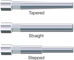
Change the thermowell profile. If structural integrity is still a concern due to fluid flow, a stepped or tapered thermowell (see Figure 3) may be an option. This retains the heavy wall section at the base but reduces it at the tip.
Figure 3. Using a stepped or tapered thermowell reduces the amount of metal surrounding the sensor.
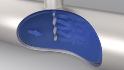
Switch to a completely different thermowell profile designed to eliminate the wake shedding formations and resulting vibrations. One thermowell design (see Figure 4) breaks up the formations so they effectively balance themselves along the length, eliminating the vibration at the source. As a result, wall thickness can be much thinner than with a conventional thermowell.
Figure 4. Emerson’s Rosemount Twisted Square Thermowell breaks up formations and allows reduced wall thickness along with long service life. Various sizes and mounting options are shown below.
If these changes are not sufficient to shorten response time, more drastic measures may be necessary. These could include moving the sensor location, increasing the number of sensors or rethinking the overall temperature regulation strategy. Fortunately, whatever the approach, the variety of temperature measurement options available can provide a workable solution.
Todd Olin is the global product manager for a group of Rosemount temperature sensor families at Emerson Automation Solutions. His educational background includes a Bachelor of Science in mechanical engineering, a Master of Business Administration and Juris Doctor, all with honors.


