Steam has been used in many processing facilities for different applications and services, and it is one of the most widely used utilities. Therefore, steam generation systems, including boilers and boiler feed water (BFW) pumps, are frequently needed in any processing plant. BFW pumps are a special class of pumps: They are relatively large, high-power, high-pressure pumps that move BFW to boilers. They are the backbone of any generation system, and they determine the pressure of the generated steam.
Although BFW pumps are a special class of pumps, some engineers think that they are simply water pumps and should be treated as such. Because of this, many failures and issues have occurred with poorly designed and supplied BFW pumps — resulting in the shutdowns of steam systems’ operation and processing facilities’ production. BFW pumps are sophisticated, and some engineers believe that BFW pumping is the most difficult water pumping service. BFW pumps are special-purpose pumps when compared to those in different process services. In many applications American Petroleum Institute (API) pumps are used for BFW services, although non-API, special-purpose pumps have also been successfully operated in many BFW applications.
In most processing plants, two identical BFW pumps — one operating and another on standby — are used, although some critical plants may have three — one steam turbine-driven pump for normal operation and two electrical-driven pumps for standby and startup. Other configurations of BFW pumps are operated in different processing facilities when steam generation details, requested reliability and operational costs call for them.
This article details the operation and reliability of BFW pumps in processing plants based on lessons learned and past experiences in different processing facilities, with a focus on BFW problem areas and hot topics including BFW suction systems, net positive suction head (NPSH) requirements, pump auxiliaries, control systems and overall operation. Special care is required for BFW pump system design — including suction piping, piping routing, piping sizing, NPSH determination and other critical issues.
Suction
The increase in size and the advanced pressures and temperatures required in steam generation systems often result in poor suction performance for some BFW pumps. Their suction performance should be investigated carefully for all possible operating scenarios. Transient pressure drops in the deaerator (BFW pump suction) should be calculated accurately to analyze the suction pressure and probability of cavitation. During rapid load rejections, the deaerator pressure might be (temporarily) less than the saturation pressure of the BFW in the supply piping between the deaerator and pump. As a result, some cavitation would therefore occur.
Usually no damage has been reported because of a minor cavitation. This has been especially true when the BFW pump design as symmetrical and the BFW flow was maintained through the pump. Although, any form of cavitation should be avoided to the maximum extent possible.
Deaerator operating conditions influence pressure decay and, therefore, the available NPSH to BFW pumps. A deaerator (at the suction) is at higher elevation than pumps, and it provides the static head above the saturation pressure to satisfy, with a margin, the pumps’ NPSH requirement. By arranging a deaerator at a high level, as determined by a boiler system’s steel structure, provide the available net positive suction head (NPSHA) with a sufficient margin to reach the required net positive suction head (NPSHR).
Old designs used an NPSHA as high as 2 to 2.5 times the NPSHR. For modern designs, all possible steady-state and transient conditions are considered, calculated, simulated using reasonable margins based on the plant and application details.
The small size of suction piping could increase friction because of the higher velocity, which can result in a decrease in the NPSHA at a BFW pump’s inlet. Conversely, a very large diameter of piping would result in a lower hydraulic friction with a long transit time (during which the suction pressure decays) and, consequently, a decrease in NPSH at the pump inlet. The piping size should be optimized to produce the best balance between different parameters — such as the water transit time and friction. For medium and large BFW pump systems, the suction pressure losses are typically about 0.3 bar to 0.8 bar, and the water velocity (at suction) is about 1.2 to 2.1 meters per second. Each design should be simulated carefully, checked and optimized using specific flow rates and piping geometries.
The suction performance of large BFW pumps, approximately 500 kilowatts (kW) or more, usually needs special attention. Many processing plants have asked for cavitation tests on the NPSH requirements for medium and large BFW pumps as well as all BFW pumps with speeds in excess of 3,000 rpm. Some high-pressure, high-speed BFW pumps with speeds above 6,000 rpm might require a booster pump to deal with low NPSHA issues because no practical solution is available to match the pump requirements to plant designs.
The booster pump could be a separate booster pump or a pump casing (in a BFW pump train) with a lower speed to act as a booster pump. Booster pumps are sometimes required for high-pressure, high-speed BFW pumps to ensure that, while the pump designs proceeded to economically desirable higher speeds and high heads per stage, there would be no danger of failure through cavitation. A booster might be used as a last solution, and before such a selection, all other options and potential adjustments and optimizations should be evaluated.
The steam generation system’s physical constrains should also be respected. Sometimes in a redesign or renovation project (or even a new project with some restrictions), because of the location and elevation of the BFW pump’s upstream equipment (particularly the deaerator and piping at pump suction), NPSHA values are so low that a BFW pump with a lower speed than optimum should be used to meet the NPSH requirements. Alternatively, a low-speed booster pump can be used. Double-entry pumps were offered previously to enhance the operating range, such as lower NPSH requirements. However, they are not recommended because of some operational problems.
Certain steam generation systems have arrangements made to continue for a period of time when the main steam system (and processing plant) is tripped to permit post-trip functions to be performed, particularly to provide the power and steam to auxiliaries. Checks are necessary to ensure that BFW pump suction conditions are satisfactory for transient conditions.
With respect to suction performance, an important case, often known as a "hot restart," has been identified for most steam generation systems. In this case, because of a failure or an issue in the condenser extraction system or the condenser pumping system, the condenser return is stopped, though a BFW pump continues to operate, depleting the suction deaerator. After some time (which might only be a few minutes), the unit is tripped or shutdown. In this situation, the BFW suction deaerator level may have seriously dropped. It is necessary to provide a margin on BFW pumps’ NPSHR for this type situation.
Typically for steam generation systems, deaerators have a total volume equal to about 5- to 16-minute BFW flow rates with a minimum of a 4- to 10-minute store to provide a buffer for transients and allow time to unload the plant should the condenser extraction pumps fail. As a very rough indication, the mass of water stored could be about 0.4 to 0.6 ton per megawatt (MW) of the steam generation capacity (on an average around 0.5 ton per megawatt). For example, the mass of BFW in the deaerator could be about 5 tons for a steam generation unit that provides steam for an approximately 10-MW mechanical drive and heating operation for a processing plant.
Small BFW pumps have specific issues and need even more attention. For instance, too often they need more care because of their low flow rates and different designs. There have been many cases in which small BFW pumps were overlooked and caused shutdown after shutdown and frequent maintenance. For instance, in some processing plants, there are two separate steam generation systems with two separate boilers and two sets of BFW pumps, one small set and one large set connected to a single deaerator. The small set of BFW pumps require close attention to their NPSHR under pressure decay conditions because of their low flow rates. A separate, appropriately sized suction piping could be required for any additional small-sized BFW pump system.
Piping, control & operation
A standby, high-pressure BFW pump could be kept at a relatively high temperature using different systems. One is a proper leak-in arrangement. Such a system leaks a small flow of BFW to the standby BFW pump. The leak in could be assured a positive, high-temperature flow to a standby BFW pump. In other words, this small BFW flow would ensure that the temperature of the standby pump is kept sufficiently high and relatively close to the operating temperature to avoid thermal shocks during a fast startup.
A leak-in arrangement in the simplest form often has a small orifice to leak into BFW, sometimes called a "warm-up" orifice. A leak-in arrangement needs special consideration since a greater-than-required flow could result in a waste of energy, inefficient operation and operational problems. A smaller-than-required flow could cause temperatures below expectations and thermal shock at a fast startup of the standby pump. A leak-in system, if not designed and operated properly, might offer operational problems and malfunctions. They need constant attention from reliability and operation teams. During the last three decades, many operation companies have required that BFW pumps be able to cold-start on standby. Particularly in the last decade, with improved designs and the use of advanced mechanical seals, cold startups and quick load changes (with consequent sudden temperature changes) became possible. Therefore, many modern BFW pumps can successfully achieve cold startup without leak-in or similar systems. However, in some plants, the requirement to maintain standby BFW pumps at warm conditions because of their extremely high operating temperatures and lack of operating experience may remain.
BFW pumps case study
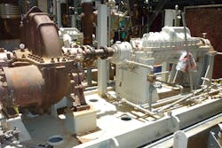
A processing plant used a high-pressure BFW pumping system for a steam generation system. The BFW pumps were API-610 pumps rated for 280-kW power with a 3,600-rpm speed. It was a horizontally-split (axially-split), multistage, between-bearings pump known as "BB3" in API arrangements. The BFW pump increased the pressure of the 160°C BFW from around 3.5 barg to approximately 73 barg. Eight impellers were used in a back-to-back arrangement; four impellers opposed the other four impellers.
On average, each impeller provided approximately a 1.46 pressure ratio. The rated impeller diameter was 238 millimeters (mm), and the selected pump model could also be operated with the maximum impeller diameter of 248 mm (approximately 4.5 percent more than rated one). The rated point was relatively close to the best efficiency point (BEP) — about 8 percent left of the BEP flow. In other words, the operating flow was approximately 92 percent of BEP flow. The pump shutoff pressure was approximately 85.5 barg, and the pump curve offered about 17 percent continuous rise from the rated point to the shutoff point.
Two pumps were used — one steam turbine (API-611)-driven operating pump and another electric motor (VSD)-driven standby pump (which was also used for the startup). The suction nozzle and the discharge nozzle were 4 inches, 900-pound, raised face (RF) and 3 inches, 900-pound, RF, respectively. The suction piping size and discharge piping size were 6 inches and 4 inches, respectively. The pump casing material and the pump shaft material were alloy-steel (12 percent chromium) and stainless steel, Type 410, respectively.
Amin Almasi is a senior rotating machinery consultant in Australia. He is a chartered professional engineer of Engineers Australia and IMechE and holds bachelor’s and master’s degrees in mechanical engineering and RPEQ. He is an active member of Engineers Australia, IMechE, ASME and SPE and has authored more than 100 papers and articles dealing with rotating equipment, condition monitoring, offshore, subsea and reliability.


