Pumps are an integral part of everyday life. They are machines that move fluids and produce hydraulic energy. Over time, pump technologies have evolved to allow pumps to process fluids of varying viscosities and properties, such as chemicals, biofuels, crude oil and solvents.
Several pumping technologies are available to operators, offering a wide variety of choices for their processing needs. They can select centrifugal, submersible, piston, or axial pumps and still have several options available. Over time, one pump technology has stood out against the others — positive displacement (PD).
PD technology has endured decades of process challenges and substances, becoming a versatile choice among professionals for its consistent performance and robust nature. PD pumps operate by pulling in fluid, trapping a fixed amount within a chamber and then forcing it out into a discharge pipe. Because of their design, PD pumps tend to have better flexibility than alternative pumping technologies when handling pressure and flow variations found in continuous or intermittent-type processes. PD pumps also operate at high efficiencies when operating conditions — such as viscosity or pressure — change, allowing them to operate at peak efficiency regardless of the conditions or environment.
Gear and vane pumps are the standouts of the PD pump line, which also includes diaphragm, peristaltic, eccentric disc and lobe pumps. These two pump variations have served as popular picks for a range of industry applications, such as manufacturing plants, tank trucks, ships, trains, storage tanks and bulk storage facilities. When it comes to these pumps, the toughest choice an operator has is deciding which one will work best in their application. It is not always a simple choice, either, as both technologies offer many of the same benefits and varying advantages.
This article takes a closer look at gear and vane pumps, examining the advantages of each and the benefits they share.
The basics
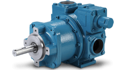
Gear pumps create flow by pushing liquid through a mesh of teeth between two rotating gears. A drive shaft moves one gear, and that motion moves the other gear. The rotating gears form a liquid seal inside the casing, creating a vacuum at the inlet as the gear teeth separate. Liquid flows into the space and moves around the outer edge of the gears. Once the teeth meet again by the outlet, the gears force the liquid out.
Gear pumps can be classified in two main categories — internal or external. External gear pumps use two separate shafts to support two interlocking gears, which form a mesh at the center of the pump to move fluid along. Common gear types include helical, spur or herringbone gears to move liquid through the pump.
A similar principle is used in the internal configuration, but with two interlocking gears of different sizes. The smaller gear rotates within the larger gear, which creates cavities for fluid transfer. An idler pin and a bushing keep the smaller gear, also known as the idler, in an off-center position, allowing it to interlock with the external gear’s cavities. A fixed, crescent-shaped spacer serves as a seal between the pump’s ports and fills the void from the smaller gear’s off-center position.
Sliding vane pumps feature a rotor with vanes that slide into and out of it as the rotor turns. This sliding motion creates chambers into which the liquid flows, and as the rotor turns, the liquid is moved to the outlet where it is discharged as the pumping chamber is squeezed down. Each revolution of the rotor displaces a constant volume of fluid with little chance for slippage, which is the very essence of a PD pump. Variances in pumping pressure have little effect on the sliding vane pump’s flow rate, and the open flow profile provides a gentle and shear-sensitive environment within the pump.
Gear up — the pros of gear pumps
Less is more — parts and maintenance
Regardless of configuration, gear pumps do not have many moving parts. The primary components in an external gear pump include two gears and two shafts. Internal gear pumps consist of a rotor (larger gear) and an idler (smaller gear), as well as an idler pin, bushing and a crescent-shaped partition.
In either setup, the number of components is minimal. Operators do not have to stockpile extra components in case of failure as there are only so few to evaluate. With few components, operators do not have to worry about keeping track of multiple moving parts and replacing them on a frequent basis.
Maintenance is also easy to perform on a gear pump. During maintenance shutdowns, gear pump operators only have a few components to evaluate and service. In many cases, service can be performed in place without the need to remove the pump from its service location. Should a component, such as a gear, fail, operators simply have to open the pump, replace the part and put it back online. This speeds up and simplifies the maintenance process, giving operators more time to focus on other tasks instead of dedicating time to an array of moving parts with different service requirements.
Robust for high temps, viscosities
Gear pumps are usually made from cast iron or stainless steel, giving the technology a robust framework to handle a variety of highly abrasive fluids with varying viscosities. They can also be made using composites or alloys, which expands their fluid-handling range. These gear pump variations can process corrosive liquids, such as sodium hydroxide and sulfuric acid, fluids that can severely damage other material compositions. Ductile iron is another material that can be used to construct gear pumps, an option reserved for reducing costs on larger pumps without sacrificing performance.
Temperature performance is a key attribute for gear pumps. Because of their robust nature, gear pumps can successfully operate in temperatures as low as -112°F (-80°C) and process fluids with temperatures as high as 800°F (425°C). This type of flexibility means varying temperatures — in fluids (surfactants, soaps, adhesives, asphalt) and atmosphere — will not hamper the performance of gear pumps. They can operate at peak levels no matter if they are processing fluids in the Arctic, the Amazon or anywhere in between.
Gear pumps also do not suffer when it comes to handling fluids across the viscosity spectrum. The interlocking gears can reliably accept fluids as low as 5 centipoise (cP) or as high as 1,000,000 cP. This is especially beneficial in process plants as operators do not have to outfit them with several different pumping technologies for varying fluid proprieties.
Gear pumps also come with tight internal clearances, the tightest of which are found in the rotor/case, rotor/head and rotor/crescent mesh. These tight clearances allow for the successful management of aggressive liquids and dissolved solids, which include paints and coatings, adhesives, sealants, rubbers, epoxy resins, detergents and food-based products like sweeteners and chocolate.
Sliding through — the pros of sliding vane pumps
Self-adjusting to wear, longer-lasting components
Sliding vane pumps leverage non-contacting rotating components that avoid material wear and sustain flow rate capacity. The contacting elements are dynamically actuated vanes, that self-adjust for wear throughout the life of a pump. This allows a used pump to sustain the same performance achieved by a brand-new pump. Time is a most essential commodity and sliding vane pumps provide operators with a pump that will retain new-pump transfer times for many years.
Sliding vane pumps sustain optimal performance throughout their lifetime by using a sliding vane design. As the vanes wear, they slide out of the rotor and continue to stay in contact with the cylinder. This means that even after many years and more than 100 million gallons of transferred liquids, internal slip will not occur, guaranteeing volumetric consistency throughout the life of the pump. This is called flow sustainment. Time is valuable, and vane pumps ensure that process times remain optimized throughout the pump’s life.
Component life is another feature of sliding vane pumps, which have a symmetrical between-bearing support design. This means the hydraulic load is supported equally on both sides, resulting in minimal shaft deflection and the prevention of cyclical deflection and fatigue. The sealing surfaces are also immediately adjacent to the bearings, making them stationary and ensuring longer seal life. The ultimate benefit of the between-the-bearing design is that no uneven loads occur, preventing wear of contacting components.
Functional benefits
By their design, sliding vane pumps do not have metal-on-metal contact. Without this form of contact, sliding vane pumps can run dry without galling or adverse effects on pump life. This means sliding vane pumps can self-prime, even if they start empty. In such a scenario, the pump can still draw a vacuum, compress the air in the piping, push it through the discharge side and draw liquid from the suction source until primed — all without damaging the unit.
The vacuum suction capacity of a sliding vane pump is also noteworthy. The pump has high suction lift to 25 feet (8.3 m), making it suited for top-offloading, underground storage or berm applications.
Because sliding vane pumps can run dry effectively and pull a strong vacuum, the technology also fits well in product-recovery applications. The pump has line-stripping capabilities, allowing operators to recover valuable product from piping and hoses. With proper product recovery, operators can save money and waste less product during recovery and cleanup.
Sliding vane pumps do not require a minimum liquid viscosity because they do not have metal-on-metal contact. This means that these pumps have a liquid-handling range from ultrathin liquids (0.2 cP) all the way up to liquids with a thickness of as much as 22,500 cP, without a drop in performance when handling thin (3-100 cP) or medium-viscosity (100-5,000 cP) liquids. Vane pumps can also handle liquids with small particulates up to 40% concentrations.
Sliding vane pumps also require no self-lubrication so both lubricating and non-lubricating liquids can be handled equally well. In fact, sliding vane pumps are renowned for operating reliably under continuous cavitation in low net positive suction head (NPSH) applications, where multi-phase vapor/liquid mixtures are expected. Whether it is crude oil or condensate, sliding vane pumps can handle them with the same pump, making this technology a champion of ultra-low viscosity and non-lubricating applications, as well as thick crude applications with suspended solids.
Fit to be equals
Both gear and sliding vane pumps excel in fluctuating systems, offering significant operational flexibility when compared to centrifugal pumps. Centrifugal pumps have a single optimized best efficiency point (BEP) and fail when operating outside of this narrow range. Unfortunately for centrifugal pumps, most applications operate across a wide range of conditions, such as fluctuations in pressure, flow rate, tank level or fluid properties. Gear and sliding vane pumps have wide performance ranges, allowing operators to sustain optimal performance consistently.
Fluid viscosity, thickness, density, vapor phase and sheer sensitivity are additional areas of advantage for gear and sliding vane pumps. Gear and vane technologies allow for a wide range of properties in each of these areas, providing flexibility for liquid type, ambient conditions and process parameters unmatched by other pump technologies.
Gear and sliding vane pumps also feature flexible sealing options, available in packed, single seal, double seal or seal-less design (a magnetic-drive). This seal-less design eliminates dynamic seals and prevents leaks. Both gear and vane are electrically driven, removing the need for compressed air needed by many other seal-less pump types. Other standout features include a vast, consistent, zero-pulsation flow range, the ability to operate at high temperatures and immunity to changes in the liquid pressure or viscosity.
Gear and sliding vane pumps also have self-priming ability, allowing them to run dry without issue. These pumps can also handle bi-directional pumping, meaning they can process fluids in either direction if required.
The composition of these pumps also serves as an advantage to both. Gear and sliding vane pumps have several options for material construction. Cast iron, ductile iron and stainless steel are three of many options available to these pump technologies. When it comes to handling difficult substances that require heat retention, such as asphalt or adhesives, both pump technologies can be jacketed across most of their surface area.
Conclusion
When it comes to selecting a pump, operators will not go wrong when choosing gear or sliding vane technologies. The key comes down to choosing a pump that best suits their needs. For operators, the best pump will balance a combination of fluid properties, system layout and performance function. Gear and sliding vane technologies offer essential functional and performance benefits that move liquids effectively and optimally.
Michael Coburn is the product manager for Blackmer Gear. He can be reached at [email protected]. Blackmer is the leading global brand of sliding vane, gear, regenerative turbine and centrifugal pump, and reciprocating compressor technologies for the transfer of liquids and gases. Blackmer is a product brand of PSG, a Dover company.


