This article discusses fan acoustics, such as fan sound, its measurement and common fan noise reduction methods.
The principal causes of fan noise are airstream turbulence and mechanical components connected to the fan. The term fan noise describes a type of unwanted sound produced by the fan or its components which may require corrective action to bring the fan sound to an acceptable level. Airstream turbulence is the primary source of airborne fan noise. In some cases it can be transmitted by the duct system to points upstream and downstream of the fan impacting the environment at the duct inlets and outlets and to areas adjacent and external to the duct system in the form of breakout noise.
Causes of airstream turbulence include:
- Resistance to flow is too high
- Flow separates at the fan blades
- Sudden changes to the flow profile (shape or velocity) as it approaches and moves through the fan
Noting that air is compressible and changes shape, locations susceptible to increased noise are:
- Unstable flow at the fan inlet
- Insufficient flow inside the wheel causing flow separation across the fan blades
- Unstable velocity vectors inside the wheel and fan housing due to surging or low flow conditions and abrupt changes in duct diameter or shape
A principal area of concern is the effect of blade pass frequency. Blade pass frequency is a pure tone produced as the fan wheel rotates past the fan outlet (or cut-off sheet) in centrifugal fans and past the straightening vanes in axial fans. This is similar to the sound heard when a moving object passes a stationary object (such as an automobile passing a person standing still). The blade pass frequency is calculated by multiplying the number of fan blades by the rotating speed of the fan wheel (rpm) as shown in Equation 1. If this frequency matches or is very close to the natural frequency of the connecting ducting, it can excite the ducting resonance and increase the noise level.
Equation 1
Blade pass frequency = (Number of blades) (rpm) / 60
Proper fan selection has a major impact on airborne noise levels. A common misconception is that the slower the fan speed, the lower the fan sound level. In some cases, this is true, but as a general rule the lowest fan sound level is achieved at the highest fan total (mechanical) efficiency. The more efficient the fan, the lower the airstream turbulence and resulting fan noise. Within wheel types, a properly selected backward inclined air handling wheel operates at lower sound levels than a forward curved, axial or radial wheel, again, because of the blade design, which allows for operation at higher efficiencies.
Mechanical components include the motor, drive and bearings, which can transfer sound mechanically to the fan or duct system through the fan shaft or structure. Since sound data provided by fan manufacturers do not include any values for mechanical components, these noise sources must be considered in addition to the published data.
Excessive vibration, although not a mechanical component, can also have a noticeable impact on noise by creating resonance with the fan/motor assembly or its mounting structure. It acts as an identifier of mechanically generated noise and is often caused by improper installation; mechanical imbalance of the fan/motor assembly; wear, fatigue or erosion of the fan; or inadequate isolation of the fan from the system ducting.
Fan sound parameters & measurement
Fan sound is measured as sound pressure (Lp), which is the change in atmospheric pressure audible to the human ear and includes all local sound sources (environmental, other machinery, etc.). It is measured at a point in space, typically using a variety of portable or fixed devices such as a sound level meter or more sophisticated equipment such as a frequency analyzer.
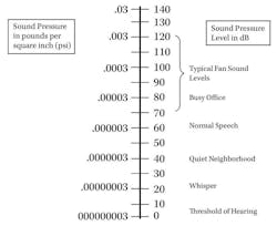
For humans, the hearing range varies from the threshold of hearing (2 x 10⁻⁷ microbar or 0 decibels – dB) to the threshold of pain (1 microbar or 134 dB). For practical application, Lp is normally scaled from microbar into dB ranging from 0 dB to 140 dB as shown in Figure 1.
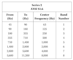
The sound spectrum is divided into eight octave bands with each octave band identified by its center or midpoint frequency as shown in Figure 2.
Using the eight octave bands shown in Figure 2, fan Lp is measured and recorded at the midpoint frequency for each octave band by the fan manufacturer using Air Movement and Control Association (AMCA) Test Standards 300 and 301. This testing is conducted in a certified reverberant or semi-reverberant room having a calibrated reference sound source to identify and remove the environmental and room noise characteristics to clearly identify the actual Lp at the midpoint frequency of each octave band (known as the substitution method). These fan Lps are then mathematically converted into fan sound power (Lw) levels, which become the primary basis for evaluating fan sound.
Lw, calculated from measured fan Lp levels using the substitution method previously noted according to AMCA standards, is used for fan sound ratings. Since it is independent of the fan environment, it is the only value specific to a particular fan, which makes it useful for evaluating fan sound levels between different fans. Note that AMCA certifies fan Lw levels with a tolerance of +6 dB for Octave Band 1 and a +3-dB tolerance for Octave Bands 2 through 8; fan Lps are not AMCA-certified.
Since sound travels in all directions, Lw is often expressed as inlet Lw, outlet Lw or total Lw. Generally, the inlet and outlet Lw levels are identical; however, when evaluating fan sound, identifying whether inlet, outlet or total Lw is being used is important for evaluation and comparison purposes. Additionally, while Lw levels are corrected for room (laboratory) environmental conditions, all other noise sources – such as motors, drives and bearings – are not included in the fan manufacturers’ Lw ratings because fans are tested without drives and with motor sound levels removed by mathematical calculations according to AMCA protocol.
Lw is the fan’s total energy (with respect to noise); referenced in watts (10-12), a function of the fan speed and point of operation (flow, pressure); and independent of the fan’s installation and local environment.
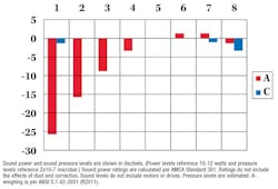
Lw is often converted into Lp using A or C scale weighting and is recorded as dBA or dBC. Since the Lw levels are independent of any installation or environmental effects (see the substitution method noted above), the Lp levels provided by the fan manufacturer in dBA or dBC will not correlate to the Lp levels measured in the field (see Figure 4).
To determine the actual fan Lp levels at the installation site, the end user must convert the Lw levels in dB to weighted fan Lp levels in dBA or dBC based on the effects of the A or C weighted scale and the characteristics of the fan’s installation and local environment. These measurements (dB, dBA and dBC) are logarithmic ratios of some measured value to a reference value, and for fans, they are normally weighted to the A scale. The A scale reduces the effects of the lower octave band frequencies to better represent the response of the human ear (see Figure 3). The A scale is used by the Occupational Safety and Health Administration (OSHA) to set maximum exposure limits, can easily be measured using a sound meter, and is calculated by applying standardized A scale weighted values to the fan’s Lw levels in dB for each octave band. An additional calculation can be performed to generate a single composite dBA value representative of all eight octave bands.
While dBA is often used for evaluating the overall sound level at a specific location, since this site measurement includes all local noise sources, it cannot be directly used to determine the actual fan sound level. Noise directivity refers to the number of radiating noise surfaces affecting a noise source at a specified distance. AMCA 303 lists directivities as Q = 1, Q = 2, Q = 4 and Q = 8 with the following definitions:
- Q1 directivity has a spherical radiation with no reflecting surfaces within the specified radius of the sphere.
- Q2 directivity has a hemispherical radiation where one reflective surface is present within the radius of the sphere (fan installed on the floor).
- Q4 directivity has a quarter sphere radiation where two reflective surfaces are present within the radius of the sphere (fan installed on the floor next to wall).
- Q8 directivity has a one-eighth sphere radiation where three reflective surfaces are present within the radius of the sphere (fan installed on the floor next to adjacent walls).
For each additional reflecting surface, the directivity factor is doubled. When specifying a required Lp level (dBA and dBC), in addition to the noise directivity factor, the distance and the direction of the control position from the noise source should be listed, such as 85 dBA at directivity Q2 at 5 feet and 60 degrees.
To accurately convert the fan Lw to Lp, the correct directivity factor and distance and control position must be applied to determine the reduction factors used to estimate Lp. Note that directivity, distance and position do not include other noise sources, such as adjacent machinery or environmental noise. These must be estimated and included to convert Lw to Lp as separate calculations. Converting Lw to Lp are outside the scope of this article, but these tools are readily available from many sources, including fan and silencer manufacturers. See Figure 4 for an example of typical fan sound data supplied by a fan manufacturer for a directivity of Q = 2 at a distance of 5 feet and a position of zero degrees.
Common fan noise reduction methods
Several methods can reduce fan noise. However, because of the many different combinations of fan types and installations, consulting the fan manufacturer and an experienced noise attenuation company is often the best practice. In site-critical installations, an acoustical consultant experienced in fan noise control is recommended.
Fan noise control is often required to meet regulatory or OSHA control limits, employee protection or comfort, and property border boundary conditions for neighboring areas. While the first measures should always be proper system design, fan selection and installation, the following measures are often used to further reduce fan noise levels:
Airborne noise
The most common way to reduce airborne noise from the fan inlet or outlet is the use of fan inlet or outlet silencers. For a silencer vendor to properly select and size a silencer, the fan performance data will need to be provided, including the Lw levels, the directivity factor, and the control distance and position. Given this information, a silencer vendor should be able to select and size a silencer that accurately meets specific sound reduction requirements. Typical reduction levels are 10 to 30 dBA. Examples of silencers are: fan inlet and outlet silencers, inlet or outlet silencer with acoustical weather cap, and single-pass absorptive silencer. Airborne sound from the fan passes through the silencer. As the sound waves enter the baffles through perforated steel, they strike the acoustic fill and are reduced.
Fan housing radiated noise
As noise passes through the fan, it also radiates through the fan housing and into the environment. The common way to reduce housing radiated noise is to add acoustical materials to the fan housing. These can either be in the form of removable acoustical blankets or applying insulating materials directly to the fan housing with a protective cladding. However, these materials only reduce the housing radiated noise and do not reduce motor or drive noise. Typical reduction levels are 8 to 15 dBA. Jackets can also be installed to the ducting to minimize breakout noise – particularly in applications with long, uninterrupted runs of straight ducting. However, a silencer, which lowers the sound transmission levels, is often the more cost- and performance-effective solution. Examples are acoustical insulation with cladding and removable acoustical blankets.
Breakout noise at the fan inlet or outlet
Breakout noise is most commonly found at fan inlet or outlet connections and sometimes occurs along the ductwork’s sidewalls. Breakout noise happens when a fitting or duct segment does not have acoustical protection, allowing the noise to break out of the fitting or ducting through radiated noise.
While flexible connectors are always recommended at the fan inlet and outlet, unless specified as acoustical connectors, they are common sources of breakout noise. Examples of fan inlet and outlet flexible connectors are: round flexible connector, flanged; rectangular flexible connector, flanged; and U-type flexible connector (round available).
Acoustical enclosures
Acoustical enclosures are normally used when all noise sources must be addressed (fan, motor and drive) or when the jobsite aesthetics require a more packaged look to the fan/motor assembly. These are available in different materials and features and are configured for the specific fan application on a case by case basis. Sound reduction levels can range from 20 to 40 dBA.
Summary
Fan noise is quantified and published by fan manufacturers as fan Lw, with estimated fan Lp levels provided based on directivity factors and control distance and position. However, to correlate this to actual field conditions, the user must use the fan manufacturer’s Lw levels and apply the correct directivity factor, control distance and position, and local site and environmental factors for an expected field sound level. Many sound attenuation devices are available to reduce airborne and radiated sound levels, but the best starting place is always good system design and proper fan selection and installation.
Reference
David Maletich, The New York Blower Company, Willowbrook, Illinois, Engineering Letter 12, “An Introduction to Fan Acoustics,” The New York Blower Company dB Noise Reduction Inc., Belvidere, Illinois.
Khalil Kairouz, Ph.D., PE, is an associate vice president for Carollo Engineers Inc., a consulting firm specializing in water and wastewater treatment. He has bachelor’s and master’s degrees in mechanical engineering from the University of Louisiana at Lafayette and a doctorate from Claremont Graduate University. He taught in the mechanical-engineering departments of Loyola Marymount University and California State University.
Dale Price is president of M&P Air Components Inc., a company specializing in ventilation and air-distribution equipment. He has a bachelor’s degree in mechanical engineering and is an active member of an American Industrial Hygiene Association taskforce on fan efficiency. He taught numerous training sessions on fan systems and their effects to the employees of state and federal agencies and private industries.


