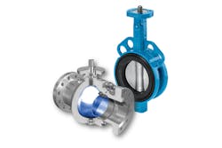
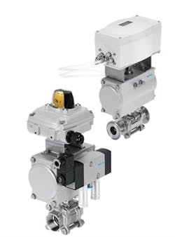
Above image: The isolating elements that controls media flow give the ball valve (left) and butterfly valve (right) their names.
Process valve automation is a crucial component of process control. In an industry driven by improved efficiency and cost reductions, a system operated purely manually is not advisable. For many facilities, valves are not typically close to each other, either being in different areas and levels of the plant or completely out of human reach.
For the automation of process valves, different applications have different requirements, so understanding which components to select and why is important. This article focuses on the automation of the ball valve and the butterfly valve because of their frequency of use and similarities.
Torque rating determination
While choosing between a ball valve and a butterfly valve can involve more than a few considerations (such as pipe size, media type/pressure and valve cost), the steps for automating them are the same. The most critical detail when building an assembly is the torque rating. Proper sizing ensures that the actuator will be strong enough to open and close the process valve when needed. Determining an accurate torque rating begins with the breakaway torque (also known as the unseating torque). This is the rotational force required to open the valve from a fully closed position. Because the isolating elements are static and have the most contact with the seals in the closed position, the breakaway torque is higher than the force needed during the valve’s normal operation at any other position, usually referred to as running or action torque.
The media pressure can affect torque requirements. Valve suppliers typically offer breakaway torque relative to the nominal pressure of the valve. In the case of the butterfly valve and the large ball valve, it is also common to show breakaway torque relative to reduced media pressures because this will help properly size the actuator for the specific application.
Safety factor application
Once the breakaway torque is determined, the next step is applying a safety factor. Some valve suppliers will give the torque rating with a safety factor already included for the application. However, unless clearly stated, end users and installers should never assume that the safety factor is included. In other instances, vendors may supply a safety factor chart as a reference to be used with the stated valve torques.
If neither of these options are supplied by the manufacturer, then the following safety factors may be used as guidelines:
Type of media
- Wet or lubricating applications — 20 percent
- Dry gas or steam applications — 30 percent
- Viscous or abrasive applications — 50 percent
Type of operation
- On/Off applications — no additional factor
- Proportional applications — 20 percent
Frequency of operation
- Daily — no additional factor
- Weekly — 30 percent
- Monthly — 50 percent
By selecting the appropriate factor from each step and adding them together, a cumulative safety factor can be applied to the breakaway torque.
Pneumatic actuator selection
Once the safety factor is incorporated into the torque rating of the valve, the next step is selecting a pneumatic actuator for valve control. Two types are available: double acting and single acting. A double-acting actuator requires air to open and close the valve. If a loss of air pressure occurs at any point, the valve will hold its last position. A single acting actuator uses air to rotate in one direction and a set of springs to move in the opposite direction. Whether the springs are used to open or close the valve depends on how the two pieces are assembled. This will also be the fail position when air pressure is lost.
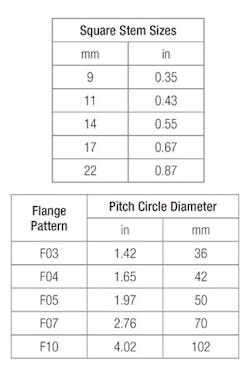
Table 1. Bolt patterns and stem sizes typically found on components adhering to ISO Standard 5211
Sizing the actuator depends on the available air pressure. The lower the pilot pressure, the larger the size required. The actuator’s torque rating must be greater than or equal to the final valve torque calculated for the application. For ease of automation, the process valve should have a direct-mount pad so that the two components can be assembled without a mounting kit. Most valve and actuator suppliers use the International Organization for Standardization (ISO) 5211 interface standard, which consists of a bolt pattern and a square stem for simple assembly.
Without this ISO Standard 5211, valve assemblies require a mounting bracket and stem coupler that can be not only expensive, but also space consuming because it increases the overall height of the unit. For the greatest flexibility, many valves and actuators come with more than one flange pattern when permissible. Table 1 shows the bolt patterns and stem sizes that are typically found on components using ISO Standard 5211.
The flange pattern of the process valve will need to be compared to that of the selected actuator. Because this interface standard is based on specific torque ranges, the two components will likely have a matching bolt pattern for direct mounting. If they do not and the actuator’s flange pattern is smaller than the valve’s, the actuator can be upsized to achieve a match. Often the cost of moving up by one or two actuator sizes is still less than the cost of a mounting kit. If the actuator’s flange pattern is larger than the valve’s, then a mounting kit is needed to connect the two pieces.
Square stem & actuator shaft size comparison
The final piece of the puzzle is the size comparison between the valve’s square stem and the actuator’s shaft. One of two scenarios is likely. The first is that the dimensions will match and the components will mate perfectly. In this case, no additional hardware is needed aside from the four bolts to attach the actuator to the valve.
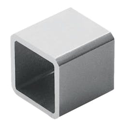
The reducing sleeve changes the square dimensions of the valve stem.
The other common circumstance is that the actuator shaft is larger than the valve’s stem. Just like the multiple flange patterns, this design is done for flexibility. A simple reducing sleeve can be placed over the valve stem to change its square dimension to match the actuator’s shaft. Though very uncommon, if the actuator shaft is smaller than the valve’s stem, consider increasing the actuator size to a point where the two components can be directly connected. The exception to this would be if upsizing causes the flanges to no longer match. Then a mounting kit will be needed regardless.
Other ball valve and butterfly valve accessories
With a process valve and corresponding actuator selected, other accessories can be added to the assembly to further automate the valve. Solenoid pilot valves use process air and an electrical input signal (coil voltage) to control the pneumatic actuator. Sensors mounted on top of the actuator provide electrical feedback that indicates whether the valve is open or closed. Positioners proportionally control the assembly via analog input signal so the valve can be opened to any angle between 0 degrees and 90 degrees. Just as the ISO 5211 interface simplifies the mating of process valves and actuators, the User Association of Automation Technology in Process Industries (NAMUR) interface (specifically standard VDI/VDE 3845) allows for these additional components to be directly mounted to the assembly with only a few bolts.
Image 1. Industrial ball valve assembly with pneumatic actuator, NAMUR pilot valve, and sensor box (right) and a sanitary ball valve assembly with pneumatic actuator and digital positioner (left)
NAMUR pilot valves can be sourced as 5/2-way for double acting actuators and 3/2-way for single acting. Most applications use pilot valves with a single solenoid coil because they provide an electrical fail-safe position and are more cost effective than the double solenoid alternative. Internal construction of these valves is typically piston spool, but if minor air leakage is a concern, a poppet design can also be sourced. Because this product is mounted directly to the side of the actuator, the response time from the moment the pilot valve is triggered to the time that the process valve shifts is almost immediate.
Sensor boxes come in different shapes and sizes, but the method of operation is always the same. The rotation of the actuator is translated into open and closed electrical signals by way of activating elements and switches inside the sensor box. The most common and cost-effective sensor utilizes mechanical micro switches. The activating elements are polymer flippers that physically press the switch when the valve reaches one of its end positions. Other examples include reed switches with magnetic activating elements or inductive proximity switches with metallic activating elements. In either case, magnetic fields are used to trigger the internal switches instead of physical contact. This helps prolong the life of the sensor box.
Proportional control of assemblies is achieved using one of three types of positioners: pneumatic, electro-pneumatic or digital. Pneumatic positioners use a purely mechanical system to reach a desired setpoint based on an air input signal, commonly 3 to 15 psi. Once calibrated, this device is accurate and efficient at reaching the correct position. The disadvantage, however, is that, to maintain the proper balance, these positioners always have a certain allowable rate of air leakage. Electro-pneumatic positioners are identical in design to pneumatic positioners with the addition of an I/P transducer which converts a current signal, such as 4-20mA, into a 3- to 15-psi air signal. Because of their similarities, these two positioners share the same pros and cons.
The digital positioner has an internal circuit board with a proportional integral-derivative controller program. As technology has improved, these positioners have become more cost effective and more accurate, commonly within 2 percent of the target. For the majority of applications, the digital positioner is a suitable alternative to pneumatic or electro-pneumatic positioners, especially when all other factors are considered. Digital positioners can be zero bleed, meaning they do not leak air when at rest. They also include an array of features — such as manual override, auto-calibration and parameter adjustment.
Valve terminals
Complete process valve assemblies, as seen in Image 1, are a widely accepted solution for process control. However, for on/off applications, there is an alternative to directly mounted solenoid pilot valves. In applications where multiple process valves are in close proximity to each other, a well-placed valve terminal would be the preferred solution for piloting those assemblies. Valve terminals can also be used in conjunction with a control cabinet in areas where electric equipment cannot be exposed to the ambient conditions. Coupled with remote I/O blocks, these diverse products provide a centralized control for the local field level components. Providing easily accessible diagnostic information simplifies both troubleshooting and maintenance.
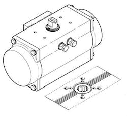
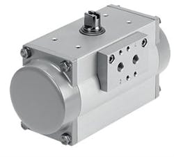
The pneumatic actuator with NAMUR (VDI/VDE 3845) mounting patterns on the side for the pilot valve and the top for the sensor box or positioner
Process valves are used across many different applications — including utility lines for cooling water, sanitary washdown for food-grade environments, and hazardous locations for the oil and gas industry. Application requirements are unique and should be reviewed on an individual basis to determine which products provide the best solution. However, process valve automation is the one sure step forward that will both improve efficiency and lower the cost of operation in any process application.
Matt Glicksman has worked for Festo in the U.S. and Canada for more than five years. Fulfilling roles in product management and engineering, process automation has always been his focus. In addition to previous experience working in the chemical processing industry, Glicksman holds a Bachelor of Science in chemical engineering. He may be reached at 631-379-6824.
Festo Corporation
