Don’t bypass overpressure protection
API 521 Section 4.4.8.1 CITATION Ame14\l 4105 (American Petroleum Institute, 2014) recommends consideration of the bypass around a control valve in the sizing of a downstream pressure relief valve (PSV). Despite this requirement, the bypass Cv might incorrectly be assumed to match the associated control valve’s maximum flow coefficient (rated Cv) during preliminary sizing of the PSV when final supplier data is not available. This assumption can lead to the PSV being undersized if the certified bypass rated Cv is greater than what was initially assumed.
This paper discusses various design options for the control valve bypass to reduce the risk of late changes to PSV sizing, and their respective advantages and disadvantages.
Introduction
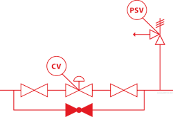
It is not always possible to design the system downstream of a control valve to the design pressures upstream of the control valve. Without a means of overpressure protection, the high pressure upstream of the control valve can overpressure the downstream system. This can result in both a safety issue, and a code noncompliance. A common means of overpressure protection is installing a pressure relief valve (PSV), which will open when exposed to high pressures and relieve flow to a safe location (flare, atmosphere, etc.) to prevent overpressure.
When a control valve is the principle restriction to flow between the high pressure and lower pressure rated systems, it can be used to determine the required relief flow and size the PSV orifice. This relief flow calculation is based in part on the rated Cv of the control valve, which can be assumed from typical values based on valve body size and specified to the supplier as a maximum allowable rated Cv. Typically in preliminary design a control valve is assumed to be one line size smaller than the piping.
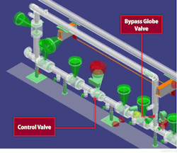
Frequently, control valves have a bypass to allow operation when the control valve is isolated for inspection or maintenance. The bypass globe valve rated Cv is typically not known when the preliminary sizing of the PSV is conducted. Despite the clear acknowledgement in API 521 Section 4.4.8.1 CITATION Ame14 \l 4105 (American Petroleum Institute, 2014) that bypasses around a control valve needs to be considered in the failure of automatic controls, designers may not give the globe valve on the bypass the same attention regarding its rated Cv.
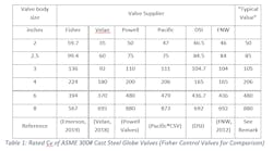
This may result in the designer assuming the bypass rated Cv equals that of the control valve for the same body size. This assumption may not be valid if a larger globe valve (>4” body as observed per Table 1, this threshold may vary based on specific vendors) is used on the bypass. This is particularly evident for an 8” Fisher ED equal percent full-sized trim control valve has a rated Cv of 567 CITATION Eme19 \l 4105 (Emerson, 2019) and an 8” Pacific ASME 300# cast steel globe valve has a rated Cv of 873 CITATION Pac \l 4105 (Pacific®CSV). If the 8” Fisher control valve rated Cv was assumed for the bypass valve when sizing the PSV, yet the Pacific globe valve was installed on the bypass, then the PSV could be undersized. This can result in in unexpected changes late into the project (either to the bypass or to the PSV and associated piping). The remainder of the paper addresses this concern and provides options that can be used to design the control valve bypass to minimize the risks of unexpected late changes.
Option 1 – Specify a “typical” globe valve rated Cv for the bypass when sizing PSV.
Table 1 shows the rated Cv of various ASME 300# cast steel globe valves, with Fisher ED equal percent full-sized trim control valve for comparison. Note this table only focuses on ASME #300 cast steel globe valves but could be developed for other ASME flange rating globe valves.
Note that the "typical" globe valve Cv is selected such that it is conservative.
As indicated in Table 1, the rated Cv of 300# globe valves are comparable between suppliers. Therefore, a designer can develop a “typical” rated Cv list for globe valves which in turn can be used for the bypass in the preliminary sizing of the PSV. In the same fashion that a maximum allowable rated Cv is specified for the purchased control valve, the designer can also specify a maximum allowable rated Cv for the purchased bypass valve. If the largest typical rated Cv for the range of available globe valve suppliers is used, then the designer may be confident that the final selected bypass valve will not require a resizing of the downstream PSV.
By developing a “typical” table like Table 1 this option allows the designer flexibility in deciding to trade operating flexibility (bypass rated Cv > control rated Cv) against oversizing the PSV relative to more a more common upset of control valve failure open with the bypass closed. While a larger bypass rated Cv will ensure the normal operating flow can be met or exceed when the control valve is out of service, an oversized PSV can result in chatter, or impacts to flare system sizing. If a smaller globe valve rated Cv is selected, then operating flexibility during maintenance will be reduced.
Option 2 – For relief valve sizing assume the bypass rated Cv is the same as the control valve. Ensure the purchased bypass globe valve has a smaller rated Cv is smaller than what was assumed.
If the designer does not have available a “typical” globe valve rated Cv (like Table 1) when sizing the PSV, they can assume the rated Cv of the bypass globe valve equals that of the associated control valve. To avoid impacting the PSV sizing later in the project the final supplier globe valve body size may have to be reduced below the original assumption. The approach anticipates a possible later revision to the globe valve body size when supplier data is available. This is probably the most frequently used approach and will likely result in loss of operational flexibility during maintenance.
Option 3 – Plan to install a restriction orifice (RO) in series with the globe valve on the bypass. For PSV sizing assume the effective rated Cv of the combined bypass and RO is equal to the control valve rated Cv. Size or remove the RO once supplier globe valves are finalized.
It is difficult to forecast if the selected globe valve rated Cv will be greater or less than the control valve rated Cv without typical values such as Table 1. In the case that the selected global valve rated Cv is less than the control valve rated Cv then a choice can be made to remove the RO. It is expected that removing a RO will have less impact to piping design/layout than adding one later.
In the case that the final supplied globe valve rated Cv exceeds the control valve rated Cv the RO allows the effective bypass Cv to be trimmed to match the original assumption used in PSV sizing. In this case full operational flexibility is maintained.
Dirty services may not allow the use of a RO due to potential plugging.
Option 4 – Install a custom designed globe valve with the same rated Cv as the control valve.
This approach will likely be more expensive and may result in longer lead times due to the speciality item orders. However, it ensures maximum operational flexibility, without oversizing the downstream PSV. This option also minimizes the risk of rework.
When pursing this approach, check if the control valve vendor can supply the same body/trim valve as the control valve with the actuator replaced by a manual handwheel.
Conclusion
A bypass around a control valve can allow for the process to maintain normal operation whilst the control valve is isolated for maintenance or inspection. For intermittent services, or other non-critical control valves the bypass may not be required. It is worth confirming with the operations team if a bypass is truly required.
It has been demonstrated that careful consideration around the bypass globe valve rated Cv can help reduce the risks of late unexpected changes.
All four options are viable solutions to help minimize unexpected late changes. In any case, the selected globe valve supplier’s rated Cv shall be checked to ensure it is less than or equal to the assumed rated Cv used for sizing the PSV.
Jonathan Webber, P.Eng Alberta, is a process engineer for Fluor Canada and a subject matter expert in overpressure protection at Fluor. Jonathan obtained his master’s degree in chemical engineering from Mcgill University (Montreal), and his Ph.D. from Dalhousie University (Halifax). He can be reached at [email protected].
Andrew Fraser, P.Eng Alberta, is a process engineer at Fluor. He has a Bachelor of Chemical Engineering from Queen’s University and a Master of Chemical and Petroleum from the University of Calgary. Andrew can be reached at [email protected]
Bibliography
American Petroleum Institute. (2014). Pressure-relieving and Depressuring Systems - API 521. Washington: API Publishing Services.
DSI. (n.d.). Cast Steel Carbon and Stainless Steel Gate, Globe and Check Valves. Stafford, Texas, USA.
Emerson. (2019, July). ED Valve - Product Bulletin. Retrieved from Fisher Control Valve: https://www.emerson.com/documents/automation/product-bulletin-fisher-ed-ead-edr-sliding-stem-control-valves-en-122396.pdf
FNW. (2012). CAST STEEL GATE, GLOBE, & CHECK VALVE FLOW COEFFICIENTS. Newport, Virginia, USA.
Pacific®CSV. (n.d.). Technical Datasheet - Cast Steel Valves. Woodland, Texas, USA.
Powell Valves. (n.d.). CAST CARBON, STAINLESS AND ALLOY STEEL VALVES. Cincinnati, Ohio, USA.
Velan. (2018). Cast Steel Valves - Gate, Globe and Check. Montreal, Quebec, Canada.


