Activate diagnostic alerts to leverage digital valve controller capabilities
Digital valve controllers provide many more benefits than a simple valve positioner, which end users can deploy to improve operations. A digital valve controller ensures the control valve position matches the commanded signal, but it also simplifies and automates valve commissioning and calibration, and it provides a means to provide significant control valve assembly data to the control system. For example, Fisher FIELDVUE digital valve controllers can detect and report degrading performance of the control valve assembly, well in advance of outright failure, but implementing a diagnostics program can be overwhelming. The simplest way to begin monitoring and analyzing diagnostics is to start small by verifying the big three diagnostic alerts are enabled.
This article describes how to enable and properly configure the three basic diagnostic alerts using a simple four-step program. By simply adjusting a few settings in their entire line of Fisher FIELDVUE digital valve controllers, users can create a highly effective means of detecting and mitigating up to 80% of control valve failures before they occur.
Digital valve controller evolution
Modern digital valve controllers are the result of a long line of innovation that started with the pneumatic valve positioner around 1949. Before that time, the control system sent an air signal to the valve, which actuated the valve directly. The air pressure required to move the valve depended on several process variables, including pressure drop across the valve, springs in the actuator, actuator design, tubing leaks and others. The usual result was that the valve position rarely matched the control system’s desired setting.
This problem was resolved with the introduction of the pneumatic positioner. The positioner accepted the control system setpoint and compared it to the actual valve position. If there was a mismatch, the positioner adjusted the air pressure to the actuator, moving the valve to the desired position. This dramatically improved process control since the valve position was much closer to setpoint, despite changing process conditions.
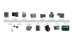
Many technical improvements have been made to valve positioners over the past decades (Figure 1), but the transition to fully digital, microprocessor controls in 1994 proved to be a significant inflection point. With this advancement, new device capabilities transitioned from valve position to true valve control, and these devices became known as digital valve controllers.
Digital valve controllers combine the elements of a positioner, sensors and associated electronics to provide diagnostics and alert monitoring. This enables a digital valve controller to not only monitor and transmit actual valve position, but to also sense supply air pressure, as well as actuator air pressure. By comparing the various sensor readings against valve position and commanded setpoint, digital valve controllers can detect and alarm when the performance of either the valve or the device itself is degrading.
But not all end users are taking full advantage of this technology in their installed base, a situation that can be rectified by following the steps detailed below.
Reliability centered maintenance
There are several strategies that can be utilized to guide a maintenance program for an operating facility. The first strategy is to simply do no maintenance until something fails and to fix it at that time. This is called corrective maintenance or run-to-failure, and while the initial costs are low, the cost of unexpected downtime and production loss can be very high, as can costs for performing the required unscheduled repairs. Despite the initial low maintenance cost, this method typically results in the highest operating cost over the long term.
The second strategy is to pull each piece of equipment and fully rebuild it on a fixed schedule chosen to avoid unplanned failure. This option, called preventative maintenance, greatly reduces costly downtime, but it creates a much larger maintenance budget since equipment is routinely overhauled, even though it may not require it. The overall cost is less than the run-to-fail corrective maintenance option, but the long-term operating cost can still be quite high.
The third strategy is called condition-based or predictive maintenance. This methodology schedules equipment maintenance based on the current condition using diagnostic technology. When equipment begins to show signs of problems, maintenance is scheduled, and repairs are made. This strategy can cost much less than the previous two options, but it is only successful if the facility has a means to determine the current condition of equipment. If developing problems cannot be detected, the equipment will fail and create unexpected downtime and production loss.
In an optimized reliability-centered maintenance program, all three strategies have their place. Letting non-critical valves run to failure often makes sense since the cost of failure is very low. Routinely pulling and overhauling low to moderately critical valves also has merit as this method avoids significant downtime and unplanned failures. The remaining moderate to highly critical valves are likely good candidates for condition-based maintenance, provided the valve condition can be ascertained, and that is where the big three digital valve controller alerts come into play.
The final strategy in a reliability-centered maintenance program is called proactive maintenance. While not specifically applicable to the topics discussed below, proactive maintenance is a method used to reduce or eliminate points of failure. For example, if a valve has problems with the trim plugging up over time, the valve can be retrofitted with a non-plugging dirty service trim, eliminating the problem.
The big three alerts
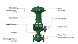
The Fisher FIELDVUE DVC6200 digital valve controller and Fisher FIELDVUE DVC7K digital valve controller can both provide basic, or advanced, valve condition diagnostics (Figure 2). Unfortunately, not all users use even the basic alerts, typically because they are not turned on or set correctly, or they are enabled and active but not monitored.
Four steps to realize full value from the big three alerts
These alerts can be activated and leveraged as part of a condition-based maintenance program by following these four steps, in order:
- Consider the impact each control valve has on plant operation and separate them into different categories of criticality.
- Connect to each digital valve controller and turn on and set the big three alerts.
- Monitor valves for new alerts.
- Act upon alerts to resolve problems.
Step 1: Consider the impact each control valve has on plant operation and separate them into different categories of criticality.
Many facilities use A, B, C and D categories, with A being most critical to the operation and D the least.
With manual monitoring, A-criticality valves are monitored about once a week, B-criticality valves monthly and C-criticality valves quarterly, for example. D criticality valves are not critical to the operation and may be allowed to run to failure. But with automated monitoring A-, B-, and C-criticality valves can all be monitored much more frequently.
Step 2: Connect to each digital valve controller and turn on and set the big three alerts.
Online brochures provide a host of detailed settings for various models of Fisher digital valve controllers, such as this one.
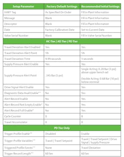
While there are many diagnostics available that can be configured, there are three simple diagnostics that should be configured for all digital valve controllers. Those settings are highlighted in Figure 3. These, and other, digital valve controller parameter settings can be accessed via a HART handheld device, or a PC connected locally or remotely to the control system.
The big three alerts cover most of the potential failure points of a valve assembly and are described in the following paragraphs.
The Travel Deviation Alert tracks the actual valve position against commanded valve position. As the valve moves, the two positions will differ, however within a few seconds, the actual valve position should match the commanded valve position within a small tolerance. Setting a 5% deviation with a 5-second travel time will work well for most valves, but very large valves may require a longer time delay setting. The travel deviation alert will usually indicate a developing problem, such as valve sticking, air loss in the system, packing adjusted too tightly, or other issues. This alert is important because a digital valve controller will typically adjust to and mask this condition, making it invisible to the operations team until the issue degenerates into an outright valve failure.
The Supply Pressure Alert monitors plant air supply pressure to the valve and alarms when the air pressure is inadequate. Single-acting spring actuators require a minimum air supply pressure equal to five PSI above the maximum operating pressure shown on the nameplate, with the alert set three PSI below that value. A double-acting actuator requires air supply pressure as indicated on the nameplate, with the alert set 10 PSI below that value. A low air supply pressure alert likely indicates a plugging filter regulator, an air leak on the supply tubing or a problem with the air supply.
The third alert is the Drive Signal Alert, which monitors how hard the valve controller is “working” to move the valve. If the valve is neither fully open nor fully closed, the drive signal should be at 55% to 85% of the nominal value. When the valve is fully open or fully closed, the air signal will either be saturated to near zero or at full pressure, respectfully. Significant deviations from these values could be caused by internal problems with the valve positioner, such as a plugging I/P, or by an out-of-calibration condition, with either activating the alert.
For these alerts to be properly logged, the alert record must be enabled, and the proper date and time entered into the valve controller. This allows time-stamped alerts to be captured and stored for later retrieval.
Step 3: Monitor valves for new alerts.
Configuring the alerts is clearly an important step, but the alerts have little value if they are not detected and acted upon. Early versions of the digital valve controller have limited ability to store alerts, so if they are not routinely viewed and cleared, the alert record will fill up and cease to store any new data. New models, such as the DVC7K, have a much larger memory and automatically overwrite old data with new data once the buffer is full.
Regardless of the digital valve controller model involved, a key part of this process involves monitoring the valves for new alerts and addressing issues as they are indicated. If the facility has a HART-enabled maintenance program, it can be used to remotely detect alerts and pass them to the maintenance technicians. If no such communications network exists, a routine manual scan of each valve may be required.
Step 4: Act upon alerts to resolve problems.
Top performing plants have processes where an active alert will generate a work order in the computerized maintenance management system. The technician responsible for clearing the alerts needs to be trained in basic troubleshooting methods to determine what is causing the alert so that the problem can be corrected before it causes a failure and the alert cleared.
Key takeaways
The big three alerts can detect up to 80% of control valve failures, providing a simple and effective means of detecting the current operating condition of each control valve. With this information, successful implementation of a condition-based monitoring program is accessible to all. If a HART-based maintenance software system is available, alert monitoring can happen automatically.
Many plants have spent hundreds of thousands of dollars to purchase top-tier digital valve controllers to keep their process running smoothly. However, some of those same facilities fail to utilize the basic diagnostic features that already exist in those devices. Nearly every Fisher digital valve controller simply requires a few parameter changes to begin detecting and logging alerts that can flag up to 80% of degrading valve performance, well in advance of outright failure. By performing the four steps detailed above, facilities can achieve significant improvements in control valve uptime and reliability, with no expenditure required for new equipment.
About the Author
Mark Nord
Control valve solution architect for Emerson’s Flow Controls Products
Mark Nord is the control valve solution architect for Emerson’s Flow Controls Products in Marshalltown, Iowa. He is responsible for solving the most challenging control valve applications using his 35 years of experience in plant operation, control valve and steam conditioning applications. Nord holds a BSME degree from the University of North Dakota.


