Monitoring pressure relief valves as part of a digital ecosystem reduces cost and improves performance
Any kind of pressurized system, from a residential hot water heater to a massive chemical reactor, will have some sort of pressure relief mechanism. It’s there to let internal pressure escape before it overcomes the mechanical strength of the equipment. This concept is as old as the earliest steam boilers and is the last line of defense in an overpressure event to protect people and equipment.
Industrial plants, such as refineries and chemical processing facilities, have hundreds of pressure relief valves (PRVs). Each needs to be matched with the size of the processing equipment and its ability to generate pressure. A PRV may never be called upon to operate in an emergency, but when needed it must perform in a very specific manner. If pressure can’t be released faster than it can be generated, then the valve is too small. If the valve is too large, it could become unstable during a release.
Opening reliably when system pressure reaches the selected level is the most obvious qualification, but it is not the only factor. PRVs are designed, manufactured, sized and selected to fulfill requirements of specific codes and standards. They are of special interest to the many jurisdictions charged with enforcement of local laws and standards, as evidenced by the way they are highlighted in the National Board Inspection Code: “The most important appurtenances on any pressurized system are the pressure relief devices provided for overpressure protection of that system1.”
As safety devices, PRVs are mechanically self-operating without the need for any electronic components or external support to function. Consequently, they are typically off-grid with no built-in mechanism capable of reporting their condition or activity via an emergency shutdown system (ESD) or distributed control system (DCS). If operators want to know what is happening with a particular PRV, they typically rely on local inspection or monitor normal process pressure measurements for indication of operation near the PRV’s setpoint. There are mechanisms that can be added to monitor PRVs, which we’ll discuss later in the article, but let’s first take a look at some PRV design details.
Types of PRVs
The two most common PRV designs are direct spring load and pilot operated.
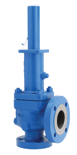
Direct spring load — Often referred to as “pop valves” (Figure 1), these devices are held closed by direct spring pressure, so their operational characteristics are directly affected by changes in system pressure. They pop open at a specific set pressure, driven by the system pressure and volume. When pressure falls back to below the opening point, they self-reseat, and can go through this cycle any number of times. If the system pressure remains close to the set pressure for an extended period, metal-seated valves tend to allow momentary or continuous low-level releases characterized as “simmering.” This is the most widely used design.
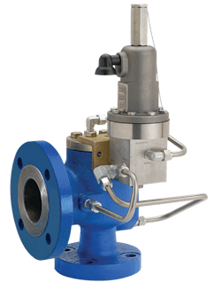
Pilot operated — Here the main valve seat is held closed by the system pressure itself (Figure 2). When the pilot senses that the set point pressure has been reached, it opens and reduces the dome pressure, which causes the main valve to open. There is no simmer in the main valve and very little in the pilot. Pilot valves are normally soft-seated and can operate closer to set pressure than direct spring valves. Pilot valves also have the option to provide modulating action wherein the valve opens slowly, behaving like a back regulator or control valve. Modulating action pilot valves respond when inlet pressure equals set pressure by opening just enough to hold inlet pressure at the set point, minimizing wasted product and emissions.
Discharging to atmosphere versus an enclosed system
PRVs might release process fluids to the atmosphere if the products involved are environmentally benign, but more often individual relief points feed into a system to collect liquids while diverting gases to a knockout drum, recovery system or flare. Any product released will typically be unrecoverable or downgraded to a less valuable application, such as feeding energy to boilers and furnaces. This adds to the cost of an incident, along with possible environmental consequences and fines.
Since the header connection covers the PRV discharge pipe, determining which PRV is open may not be clear to operators trying to troubleshoot the situation. Operators may also be uncertain because normal process operating information will likely be inconclusive. Unless there is a clear overpressure incident in progress that is visible in the control room through process data, the problem may be more subtle.
With an enclosed system, it is often not possible to see if a valve does not fully reseat itself and close completely after an overpressure incident. The valve mechanism inside a PRV of either type could be seated incorrectly, leading to a standstill leakage. Such leakage may be so small as to be undetectable by process instrumentation, such as pressure transmitters and flow meters. For hours and perhaps days, product could be flowing to the recovery system unnecessarily, reducing production and plant profitability. How can troubleshooters determine when this is happening, and what specific PRVs are affected?
Monitoring PRVs
Monitoring the condition and activity of PRVs and rupture disks should be a part of normal plant operation, but as mentioned, there are no mechanisms within the devices capable of sending information to an automation system. Consequently, an external monitoring device must be added that will not interfere with its ability to open, using an approach matched to the valve type for best results.
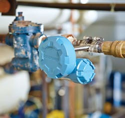
Acoustic monitoring devices equipped with WirelessHART transmitters (Figure 3) are now available and designed for mounting directly to pipes adjacent to valves, direct spring load PRVs, pilot operated PRVs, steam traps and other common fluid handling equipment. They sense vibrations in the discharge pipe due to turbulences generated by fluid flowing through the valve and transmitted directly through the pipe wall. This turbulence generates a wide range of frequencies, but acoustic transmitters concentrate on ultrasonic frequencies transmitted as mechanical vibrations in the pipe that are easy to distinguish even in environments where ambient noise is a concern.
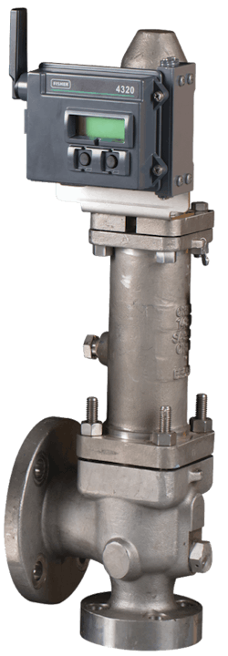
A wireless position monitor can measure the amount of lift on direct spring valves and log the time and duration of a release event. By multiplying the orifice diameter of the valve and the amount of lift, it is possible to calculate the volumetric release of each relief event (Figure 4).
Pilot operated PRVs can use a different monitoring approach. Because a pilot operated PRV requires system pressure as the holding pressure to keep the main valve closed, the system pressure and holding pressure should be equal when the valve is closed. Using a differential pressure (DP) transmitter and reading the difference between the system and holding pressure provides reliable monitoring. If the holding pressure drops, the main valve will open. A WirelessHART-equipped DP transmitter can make installation simple, quick and far less expensive than a conventional wired transmitter. By interpolating the intrinsic characteristics of the valve with the DP measurement, it is possible to gauge the flow passing through the main valve.
Small leak, large loss
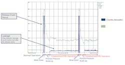
With both types of PRVs, a fully closed valve makes no vibration due to turbulence because nothing is flowing through it. When system pressure exceeds the set point, it opens, releasing the contents of the system — liquid, gas or both. This creates turbulence, generating mechanical vibrations that an acoustic monitor can detect and report to the automation system.
If the process recovers and system pressure returns to normal, or operators reduce pressure sufficiently, the PRV should close again automatically. If everything is working correctly, it will seal, and the mechanical vibration will cease. Data from the acoustic transmitter can verify the action, reporting the time the discharge began and ended, while giving some approximate indication of how serious the discharge was based on the amplitude of the sound.
But sometimes things go wrong and a small particle of debris from the process can get in between the valve and its seat, causing leakage (Figure 5). This can happen with either type of valve but tends to be more of a problem with direct spring load metal-seated PRVs. Pilot operated PRVs have soft seats and are not as likely to trap debris, but it can still happen, therefore some users install acoustic transmitters on pilot operated PRVs as well.
Like a full overpressure-driven release, small leakages also generate turbulence inside the discharge pipe, causing mechanical vibration detectable by the acoustic transmitter. Usually, the amplitude of a leakage detection is smaller than a full release, which helps differentiate these two events via measurements from a single acoustic transmitter.
The importance of detecting leakage as soon as it starts is driven by the compounding effect over time. A mere 0.1% leakage, if left unaddressed for a year, equals a full release from a PRV for six hours. The effect is multiplied into a huge problem when considering the total population of PRVs in a process unit or overall plant. A study from 10,000 PRV service records presented an astonishing result indicating that 20% of installed PRVs leaked below 50% of set pressure, so many valves may have been leaking all the time. Even worse, 8% of valves surveyed leaked so excessively they did not pop correctly in the test.
Often, the main root cause for continuous PRV leakage is leakage itself. Over time, undetected releases cause wear and compromise valve seat integrity, which makes the leakage worse. Because such leakage is undetected, it receives no maintenance attention and simply continues. Undetected and unreported PRV releases occur more often than operators realize. PRVs are the silent sentinels protecting against catastrophic overpressure, so their releases should be reported and recorded as near-miss safety incidents for process safety root-cause analysis.
Managing maintenance and optimizing
PRV spares pools
Many process facilities maintain installed populations of PRV’s measuring in the thousands to protect equipment and personnel. As safety devices, these valves must be ready for duty at all times, and accordingly are often subject to mandatory testing, inspection and repair cycles. The challenge is to provide a high margin of safety while minimizing the costs associated with maintaining PRVs.
To reduce maintenance costs and the associated inspection and testing activities, many end users have found an effective strategy is to use spare PRV pool programs. Redundant valves that mirror the installed PRVs are purchased and kept in storage, ready for quick exchange when the installed PRV is removed from service (Figure 6). This strategy allows PRVs to be prepared for installation well in advance of a planned turn-around, minimizing and simplifying the work to be performed during the outage.
This approach also minimizes the time employees are exposed to possible safety hazards created when working on scaffolding or other potentially dangerous situations. After the in-service PRV is removed, it is returned to the shop for inspection and refurbishment, and then it goes back into the spares pool where it can be used when needed.
Combining historical maintenance records with online monitoring data supports development of predictive maintenance programs. Decreasing relief events and detecting PRV leaks minimizes product losses, reduces energy usage and extends equipment lifecycles. One Asia-Pacific refinery saved $500,000 per year by reducing hydrogen loss after detecting and repairing leaking vent valves and PRVs. At a U.S. refinery, PRV monitoring resulted in an ROI of 271% after correlating relief events against process data. Another U.S. refinery is now saving between $2,500 and $50,000 for every hazardous material relief detection.
Monitoring PRVs via WirelessHART networks
PRV monitoring transmitters can use the same WirelessHART network as other wireless field devices. This allows PRV monitoring transmitters to interface with a larger process automation system if desired, while also sending data to the reliability and maintenance team. With continuous monitoring, technicians can tell in an instant if a pressure release is underway, if a valve has not fully reseated or if a rupture disk is starting to fail.
Digital ecosystem applications, such as Emerson’s Plantweb Insight for PRVs (Figure 7), are ready-to-use solutions able to characterize a release event by interpreting information from an acoustic transmitter, valve position monitor or DP transmitter. This helps eliminate guesswork by operators and false positives. They also require electronic acknowledgement of what action was taken when after an event. This is critical information not just for environmental compliance, but also to supply data into the larger PRV maintenance management program.
With prompt action, the overall effectiveness of a process unit’s safety system can be assured while avoiding product loss and potential environmental consequences. Many equipment condition monitoring devices are now available to determine how well various types of assets are functioning. This information can help optimize maintenance efforts and avoid costly unplanned shutdowns.
References
- National Board Inspection Code, Part 2, 2.5.1
Marcelo Dultra is a process industry director for Emerson’s Automation Solutions business in Houston, Texas, specializing in pressure relief valves. He has more than 25 years of experience in process automation and safety systems. He received his bachelor’s degree in electrical engineering from Unicamp in Brazil and his MBA from Texas A&M. Marcelo has worked in multiple projects involving digital integration, fieldbus networks, safety systems, partial stroke testing, and wireless valve monitoring.
Marcio Donnangelo is a global business development manager with Emerson’s Automation Solutions business in Houston, Texas, specializing in wireless technologies. He is an industrial electrical engineer with 25 years of field experience applying industrial automation solutions for customers across multiple business segments and industries including refining, petrochemical, chemical, pulp and paper and others.
