By Brad Buecker
Interest in combined heat & power (CHP) keeps growing. Electric-power and process-steam co-production has proved economical at refineries, petrochemical plants and pharmaceutical facilities. Net efficiencies up to 80 percent are said possible.
However, if water & steam treatment is mishandled, plants instead face outages and unit shutdowns.
Combustion turbines (figure 1) with heat-recovery steam-generators (HRSGs) for CHP steam generation are increasingly common, e.g., replacement of coal-fired electricity generation.
Combustion turbines, like jet engines, execute a fundamental thermodynamic cycle, the Brayton Cycle.
- Inlet air is compressed and injected into the turbine. The compressor is attached to the turbine shaft, and thus the compressor and turbine rotate in unison.
- Fuel, typically natural gas but occasionally fuel oil, is injected and ignited in the compressed air stream.
- The expanding gas drives the turbine.
- Hot exhaust, at 850 F or higher, exits the turbine.
Key advantages for power industries include fast start times, especially during peak power periods; low capital cost compared to coal or nuclear; simplicity of fuel feed; and minimal operations and maintenance issues. For wind and solar power production, fast-start backup helps when temporal conditions limit renewables supply.
Combined-cycle energy generation
A stand-alone combustion turbine’s net efficiency is at most 30 to 35 percent, with much energy loss from the turbine exhaust. This is where the combined-cycle design helps. A heat-recovery steam generator (HRSG) placed at the turbine exhaust produces steam using waste heat. The most common HSRG design is the multi-pressure, drum-type unit (figure 2).
As shown, the condensate is split between circuits, with relatively small flow to the low-pressure (LP) steam network and the bulk to the intermediate- (IP) and high-pressure (HP) circuits. Steam extraction may be taken from any circuit, or, as is most efficient, from a non-condensing turbine.
For straight steam production with no steam power generation, a less complex scenario is perhaps better with a combustion turbine and a single-pressure HRSG.
Net efficiencies of combined-cycle units for power production today may reach 60 percent, while up to 80 percent efficiency is reportedly possible for co-generation.
However, the author’s experience at facilities where power production is only part of the process reveals that water & steam treatment and chemistry monitoring are too often neglected. This inadvertent negligence will haunt operators and technicians once water & steam side upsets — either short- or long-term — lead to corrosion, scaling, and fouling failures of potentially enormous cost.
Sometimes troublesome condensers
Regarding water/steam chemistry in dedicated power-generating units, the condenser is typically the most troublesome source of contaminant in-leakage. Impurity introduction via condenser tube leak can cause boiler tube failures within weeks, days or hours. Most notorious is chloride, which in the steam generator concentrates under deposits, causing acidic corrosion and hydrogen damage.
On-line monitoring of condensate chemistry is essential to detect impurity ingress.
Unless a steam generator’s condensate/feedwater system contains copper alloys, oxygen scavenger use is highly discouraged. These are now known to propagate flow-accelerated corrosion (FAC) in feedwater systems, economizers and low-pressure HRSG evaporators, amongst other locations. Within the last three decades, FAC-induced failures have caused power plant fatalities. Up-to-date programs use ammonia or sometimes an amine for pH control, but allow oxygen leaking in through the condenser to remain. This oxygen, when chemistry is carefully controlled, causes the carbon-steel feedwater piping to develop a protective oxide layer.
Still popular for boiler-water treatment, especially in high-pressure units, are tri-sodium phosphate (Na3PO4) and caustic, which boost alkalinity and help neutralize bad actors such as chlorides. However, overfeed can lead to other chemistry problems, including under-deposit caustic corrosion. Careful attention must be given to steam chemistry. Even trace amounts of impurities can damage downstream equipment, particularly turbines. Common limits for chloride, sulfate, and sodium in steam that supplies a turbine may be as low as 2 parts-per-billion (ppb).
Condensate return chemistry
For CHP plants distributing steam to process heat exchangers, district heating, or other similar applications, condensate return chemistry is critical. First, some boiler-water chemistry programs — particularly in low-pressure units with relaxed chemistry requirements — allow CO2 to carry over with steam. This CO2 then condenses with water in the condensate return system, generating corrosive conditions, as will any oxygen carried over or otherwise entering the condensate return system.
Condensed steam may collect impurities, including iron oxide and other corrosion products, organic compounds and non-metallic suspended solids. Condensate filtration and polishing are often mandatory preparation to return this water to the steam generator, using techniques that may include filtration by activated carbon, particulate filtration by membrane or disk media, and ion exchange.
Also often overlooked is damage occurring during shutdowns. Improper steam generator layup, and subsequent unit air in-leakage, can initiate excessive corrosion that not only damages components but generates corrosion products that migrate to the steam generator and deposit on boiler-tube surfaces.
Ideally, for short-term shutdowns where water remains in the steam generator, nitrogen blanketing protects the system from air in-leakage. If this isn’t an option, other wet lay-up procedures should be established.
Reliable technologies are today available to remove dissolved oxygen from steam-generator fill-water. This is important, particularly for units facing frequent shutdowns and layups, and where demineralized water and condensate are stored in atmospherically vented tanks.
Cooling water issues
The second law of thermodynamics indicates that, for any process, not all the heat produced to drive the process will be converted to work. Besides losses due to natural properties, some heat is system-rejected. The most common locus of heat rejection in industrial plants are the cooling towers, or some version thereof, such as a wet surface air cooler (WSAC). In the following, we focus on only a few key cooling-tower issues.
The cold water coming out of the cooling tower is that which returns to the plant heat exchangers. Efficient tower heat transfer is vital for plant efficiency. Cooling tower efficacy, however, is very much influenced by how intimately air and water are brought into contact in the tower. This is a direct function of the fill material in the tower. Poor fill selection or design, or poor cooling water treatment, can lead to significant problems.
Fill used in early cooling towers was splash fill, where circulating water cascades down and onto slats within the tower. Splash-fill technology has considerably improved, and a modern design has plastic slats material, as opposed to wood.
The impingement process breaks up water droplets to increase water-surface area. Slats are arranged in a staggered formation to maximize air-water contact. Splash fill is common in crossflow cooling towers where the air travels perpendicular to the water spray. Splash fill may be the design of choice in cooling towers when the water has a high fouling tendency.
Film-fill preferences
In the majority of towers, however, film fill is preferred.
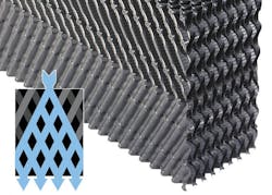
Film fill, as the name implies, induces the cooling water to form a film on the material surface. The filming mechanism maximizes liquid surface area. One might be tempted to think that film fill is generic in nature and that just any type can be installed in a tower. Such is not the case. A guiding principle behind fill design and selection is "to increase air-to-water contact, driving up convection and evaporative cooling while reducing pressure drop in the system." Typical fills are made of PVC because of its low cost, durability, good wetting characteristics and inherently low-flame spread rate. Factors that influence fill performance, neglecting for the moment fouling or scaling within the fill, include the flow-path arrangement and flute size, i.e., the size of the openings in the fill. Three major fill configurations are illustrated below.
In the first design, as is clearly evident, water flow is dispersed laterally upon entering the fill, thus providing a very large surface area for air interaction. Progressively simpler fills are not as efficient, but are less susceptible to fouling.
Regardless of fill choice, chemical and mechanical control of corrosion, scaling, and fouling are still extremely important. Of the three, microbiological fouling is often the most problematic. Cooling systems provide an ideal warm and wet environment for microbes. Bacteria grow in condensers and cooling-tower fill; fungi is found on and in cooling-tower wood; and algae persists on wetted cooling-tower components exposed to sunlight. Biocide treatment is absolutely essential to maintain cooling-system performance and integrity.
Bacteria may be aerobic, and use oxygen in the metabolic process; anaerobic, and live in oxygen free environments and make use of sulfates, nitrates or other energy donors; or facultative and able to live in either of the two previous environments.
Slime-secreting bacteria
Once microbes, and particularly bacteria, settle on a surface, the organisms secrete "slime," i.e., a protective polysaccharide layer, which grows even thicker by collecting silt from the water, further reducing heat transfer. Even though the surface bacteria may be aerobic, the secretion layer allows anaerobic bacteria underneath to flourish. These bugs in turn generate acids and harmful compounds that attack the metal. Microbial deposits also establish concentration cells, where the lack of oxygen underneath the deposit causes the locations to become anodic to other areas of exposed metal. Pitting is often a result, which can cause premature tube failure.
Fungi will attack cooling tower wood in an irreversible manner, eventually leading to structural failure. Algae will foul cooling tower spray decks, potentially leading to reduced performance and unsafe working locations.
Most microbiological treatment programs feed an oxidizing biocide to kill organisms before they settle on condenser-tube walls, cooling-tower fill or other locations. Chlorine was the workhorse for many years, where when gaseous chlorine is added to water the following reaction occurs.
Cl2 + H2O → HOCl + HCl
HOCl, hypochlorous acid, is the killing agent. The functionality and killing power of this compound are greatly affected by pH due to the equilibrium nature of HOCl in water.
HOCl → H+ + OCl-
OCl- is a much weaker biocide than HOCl, probably due to the fact that the charge on the OCl- ion does not allow it to penetrate cell walls. The killing efficiency of chlorine dramatically declines as the pH goes above 7.5. Thus, for the common alkaline scale/corrosion treatment programs, chlorine chemistry may not be efficient. Chlorine demand is further affected by ammonia or amines in the water, which react irreversibly to form the much less potent chloramines. Chlorine also reacts with organic materials to form halogenated organics, which are a safety concern.
Due to handling and personal safety issues, liquid bleach (NaOCl) feed has replaced gaseous chlorine at many facilities.
A common alternative is bromine chemistry, where bleach and a bromide salt, typically sodium bromide (NaBr), are blended in a makeup water stream and injected into the cooling water. The chemistry produces hypobromous acid (HOBr), which has similar killing powers to HOCl, but functions more effectively at alkaline pH.
Chlorine dioxide (ClO2) is becoming more popular for several reasons. Its killing power is not affected by pH, the chemical does not react with ammonia, and it does not form halogenated organic compounds. Also, chlorine dioxide is more effective in attacking established bio-deposits. The chemical must be produced on-site, but new methods make this process much easier than in the past.
Brad Buecker is a process specialist with Kiewit Engineering and Design Co., in Lenexa, Kansas. He has nearly 35-years’ experience with the power industry, in chemistry, water treatment and air-quality control positions. He has a B.S. in chemistry from Iowa State University with additional course work in fluid mechanics, materials and energy balances and advanced inorganic chemistry. Buecker is a member of the ASME Research Committee on Power Plant & Environmental Chemistry and the program planning committee for the Electric Utility Chemistry Workshop. He can be reached at [email protected].


