As its name indicates, Evergreen Community Power LLC (ECP) in Reading, Pennsylvania, is focused on staying green. With its energy-efficient boiler and steam generator, the facility can produce 33 megawatts (MW) in a combined heat and power facility using biofuels. The biomass plant’s electricity and steam output supports the manufacture of 350,000 tons of kraft linerboard per year and 180,000 tons of recycled corrugated medium per year.
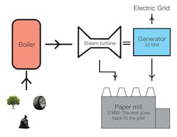
Fundamentally, this power plant is comprised of a boiler with a steam turbine and generator. The circulating fluidized bed boiler produces 330,000 pounds of steam at 1,200 psi with a thermal efficiency of 87 percent. The steam from the boiler is directed to an extraction, condensing steam turbine.
The three turbine extractions allow precise control of the paper mill and plant’s parasitic loads. The turbine condenser maximizes the amount of electricity produced from the excess steam. The generator is rated for 33 MW, much larger than the attached plant and mill electric loads. When it is economically favorable, the power plant generates excess electricity and sells power back to the grid.
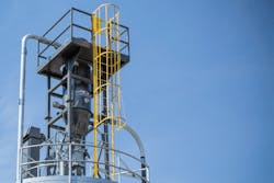
The power company’s green focus carries over to how it handles the two kinds of ash byproduct created by biofuels or wood burning. Bottom ash is a non-combustible residue that falls through the bottom of the boiler, and fly ash is driven through the boiler and escapes with the flue gasses where it is separated, transferred and stored in a 2,000-ton silo.
Previously the plant carted the residue to a landfill at a rate of approximately 40 semitrailer loads of fly ash per day, costing more than $1 million per year.
That process changed when Evergreen Compounding, a division of ECP that provides plastic products (compounds and/or master batches) made with renewable energy, came on the scene. The division was formed to convert the landfill product (fly ash) into sustainable and recyclable wood filler. The new product, BioFill, reduces virgin plastics usage and replaces natural minerals used to convert plastic products.
The issue
Now that the fly ash had a use, one problem remained for the power company: The compounding facility was more than 800 feet away from the fly ash storage silo. Trucking the material from the storage silo to a day silo was cost-prohibitive and took too much time. To effectively serve the compounding operation with a reliable supply of fly ash, the power company sought a company that could design and manufacture a complete pneumatic material transfer system.
Numerous firms could deliver all the necessary parts for a 4-ton-per-hour (tph) ash transfer system in the typical 20- to 22-week delivery period. However, ECP was in search of a design-build company that could also provide the knowledge for building a harmonistic system.
Its team selected Air Dynamics Industrial Systems Corporation to provide services from concept through delivery, startup and commissioning, which included building the 4-tph fly ash pneumatic transfer system and top-loading filter receiver.
The fly ash transfer system had to move the material at a rate of 4 tph with a bulk density of 55 pounds per cubic foot (lbs./ft.3). The fly ash was introduced into a piping system at the base of the 2,000-ton storage silo to a day silo located 550 feet horizontally and 65 feet vertically away. The horizontal pipe followed a unique path, incorporating 10 different, non-standard piping bends and two elevation changes to not interfere with raw material receiving.
Upon reaching the ash air/material separator, the product fell through a double-dump type true air lock. More unique than a rotary type valve, the device causes little to no leakage as the material dispenses from the pneumatic receiver into the day bin even when the pressure differential is more than 12 inches of mercury.
In addition to the pneumatic transfer system, the power company needed a bin vent to facilitate venting of the air displaced as fly ash filled the day silo. The bin vent filtration had to comply with the strict environmental limits within the city of Reading.
Fly ash pneumatic transfer system deliverables
- Complete pneumatic conveying system design, build and commissioning
- Application — Woodchip cyclone fly ash conveying system
- Maximum conveyance rate — 5 tph
- Design conveyance rate — 4 tph
- Total distance — 550 feet horizontal
- Material — Bulk density — 55 lb./ft3
- Ash temperature — 120ºF
- Pneumatic transfer system design and manufacture
- Mechanical installation guidance
- Electrical installation guidance
- 2D installation CAD drawing and process and instrumentation diagram
- Services — Written sequence for pneumatic conveying system for programmable logic controller, startup and commissioning
- 3D-CAD equipment general arrangement drawings
- Installation assistance — Technical support
- On-site installation training
Once the product reached the day silo, it was conveyed another 250 feet to the compounding and blending area.
“At our power plant, we take construction materials such as wood, tires and small bits of plastic…and burn that in a boiler to create power for both this facility and to provide to the public,” said Lee Samuelson, an engineer at ECP. “Before the compounding facility was built, we were moving many tractor-trailer loads of both bottom and fly ash to the landfill. We take a waste product and transform it into a usable consumer product.”
System operation
The pneumatic material transfer system design incorporated a vacuum type instead of a pressure type conveying system. Since the material is abrasive and contains about 20 percent silica, a vacuum system lends itself well to any inward leaks that may develop because of abrasion.
Material is entrained at the main storage silo where fly ash is metered or fed into the 5-inch convey line. Pickup velocity is approximately 3,600 feet per minute.
Motive air is produced by a constant volume variable pressure pump. Pumps like this have mechanical clearances of 0.004 inch or four-thousandths of an inch. This makes them ideal for long piping runs and troublesome materials. As the material resists, the pump persists – the pressure rises to overcome clogs and large irregular pieces of ash. As the material moves through the pipeline, the rarefied air expands and accelerates as it moves toward the positive displacement pump. Material enters the air/material separator radially via a silo inlet to reduce wear on internal mechanical components.
Since the power company site had very stringent environmental criteria for exhausted process air, polytetrafluoroethylene membrane media was a necessary selection to meet environmental regulations. Prior to air entering the pump, a safety filter prevents damage in the event of a primary filter failure.
A challenge for any type of vacuum conveying system arises at the point where the conveyed product dispenses into a receiver or hopper that is at atmospheric pressure. A rotary type valve presents challenges because of clearances at the rotor housing, so the designer must take adequate precautions to prevent leakage and wear at this point in the system. Flap type valves are good choices for vacuum-conveyed abrasive material. The fly ash is dispensed into a silo at atmospheric pressure. A bin vent on the silo served to filter air displaced because of the 145 ft3 of fly ash conveyed per hour.
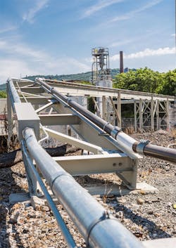
The 4-tph pneumatic piping bridge (foreground) and filter receiver/separator installed on the day silo (background).
Energy requirements
The energy required to move 8,000 pounds of fly ash per hour across the project distance (615 feet) is relatively insignificant. The fly ash transfer system required 1 horsepower for every 350 pounds of material moved per hour. The fly ash system moves the equivalent of seven 50-pound bags across 550 feet horizontally and 65 feet vertically for each horsepower or 23 brake horsepower per 8,000 pounds of ash conveyed per hour.
Selection of the piping size for any project is a balance of pickup velocity and terminal velocity. If the pickup velocity is too low, a risk of material dropout within the pipe system arises. If the velocity is too high at pickup, the terminal velocity may erode the system components prematurely.
Automation can increase the efficiency of almost every function at a power plant. Pneumatic conveying lends itself well to automation through instrumentation.
If too much material enters the line, for example, because the material size varies, the feed rate can be slowed to compensate for the product size and density. Costs for these types of additions are minimal compared to the overall benefit.
Air/material separation
Separating air from product conveyed to a receiver via vacuum or pressure requires understanding the material characteristics as well as taking advantage of the filter manufacturer’s media specifications, experience, mathematical calculations and performance data. ECP required a warranty that the filter/receiver and the bin vent exhaust effluent would not exceed an average of 0.02 gram/dry standard cubic foot after being properly installed and maintained.
On-time delivery
The pneumatic conveying system was delivered on time and exceeded the 4-tph design specification by 2,000 lbs./hr. The project was taken from concept through delivery, startup and commissioning all with one company.
Daniel P. Lehman is president and founder of Air Dynamics Industrial Systems Corporation located in York, Pennsylvania. The company specializes in the design and manufacture of ACGIH-certified industrial ventilation systems, industrial vacuum systems, pneumatic conveying systems, CKV air scrubbers and MIL-STD-810G-compliant blowing sand and dust environmental test chambers. Lehman may be reached at [email protected].


