Pressure vessel design by analysis versus design by rule
Pressure vessels are an integral part of many manufacturing facilities and processing plants, enabling the safe storage of pressurized liquids and gases. From industrial boilers to gasoline tankers, pressure vessels operate in a wide array of potentially hazardous environments. However, if not properly designed, constructed and maintained, pressure vessels can be extremely dangerous.
Historically, numerous fatal accidents have occurred due to flawed pressure vessels. As such, pressure vessel design, manufacturing and operation are regulated by engineering authorities like ASME (American Society of Mechanical Engineers). Industry standards outline critical design parameters such as maximum safe operating pressure, temperature, safety factor, corrosion allowance, and failure modes.
History of pressure vessel design
The earliest documented design specifications for pressure vessels date back to 1495 in the book Codex Madrid I, by none other than Leonardo da Vinci. Da Vinci, which theorized the use of containers carrying pressurized air to lift weights underwater.
But, it wasn’t until the 1800s that the practical use of pressure vessels was demonstrated to store pressurized steam generated from a boiler. However, a general lack of knowledge on the design, operation and maintenance of pressure vessels led to a series of fatal accidents, killing dozens of people in some instances.
Such disasters provoked the development of the first standard pressure vessel code in 1911, which was ultimately published in 1915. This standard, known as Boiler and Pressure Vessel Code (BPVC), was later incorporated into the laws of most U.S. states and territories and Canadian provinces. Today, BPVC is widely utilized all over the globe to design safe pressure vessels for a wide range of industrial applications. The ASME Boiler and Pressure Vessel Code has mandated the use of standard design codes and procedure for developing pressure vessels exceeding the pressure value of 15 PSI.
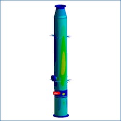
A simulation showing pressure vessel testing. (Image courtesy of Hi-Tech CADD Services)
Pressure vessel construction and key features
Although it is possible to construct a pressure vessel of any shape and size, sections of cylinder, sphere and cone are usually preferred. A more common pressure vessel design consists of a cylinder closed with end caps, known as heads, that are usually hemispherical.
Spherical pressure vessel design is typically stronger than a cylindrical shape with the same wall thickness. However, spherical pressure vessels are difficult and costly to manufacture, which makes cylindrical shape pressure vessels with semi-elliptical heads preferred in many cases.
Typically, pressure vessels are made of steel, but there are some that employ composite materials, such as carbon fiber, ceramics and polymers like PET (polyethylene terephthalate).
While ASME Section VIII, Division 1’s design-by-rule approach is most commonly utilized by engineers to size the pressure vessel according to the application requirements, it is quite a conservative approach. The empirical relations and other mandatory and non-mandatory design criteria often result in an expensive pressure vessel design.
Modern pressure vessels include safety features such as relief valves to relieve excessive pressure from the container and ensure safe operation. And most pressure vessels today are designed with a leak-before-burst feature, which enables the vessel to relieve pressure by leaking the contained fluid, rather than by means of an immediate and potentially explosive fracture.
In cases where leak before burst design is not possible, pressure vessels are required to be designed with more stringent requirements for fatigue and fracture failure modes.
ASME Boiler Pressure Vessel Code, Section VIII (Rules for construction of pressure vessels)
Most pressure vessels employed in industries today are designed according to the ASME BPVC Section VIII, which consists of standard codes and rules that a manufacturer is required to follow. More than 60 nations generally recognize and apply the BPVC for pressure vessel design. BPVC Section VIII is specifically meant to guide mechanical engineers in designing, constructing and maintaining PVs operating at either internal or external pressure exceeding 15 PSIG.
How to size a pressure vessel
A design engineer usually requires the following basic data to size a pressure vessel:
- Vessel function
- Process materials and services (corrosion, deposits, etc.)
- Operating conditions (temperature and pressure)
- Materials of construction
- Dimensions and orientation
- Type of vessel heads to be used
- Openings and connections required
- Heating/cooling requirements
- Agitation requirements
- Specification of internal fittings
Once the preliminary data is obtained, the pressure vessel design can be initiated following the standard procedures outlines in BPVC Section VIII. This section is further subdivided into subsections and appendices, guiding the engineer to determine general design requirements, fabrication requirements and material requirements to effectively size the pressure vessel.
ASME Section VIII in itself consists of three divisions, where Division 1 is focused on a design-by-rule approach and Division 2 on design-by-analysis approach. Division 3 is meant for designing pressure vessels that require internal or external operating at a pressure above 10,000 PSI.
While ASME Section VIII, Division 1’s design-by-rule approach is most commonly utilized by engineers to size the pressure vessel according to the application requirements, it is quite a conservative approach. The empirical relations and other mandatory and non-mandatory design criteria often result in an expensive pressure vessel design.
ASME Section VIII, Division 2’s design-by-analysis approach requires more detailed calculations than Division 1. Although this may increase the cost of pressure vessel design, it allows pressure vessels to withstand higher stresses.
ASME Section VIII, Division 2 is intended for purpose-specific vessels with a defined fixed location. Another major difference between the Division 1 and Division 2 lies in failure theory. While Division 1 is based on normal stress theory, Division 2 is based on maximum distortion energy (Von Mises).
The codes mentioned under Section VIII for both divisions also include appendices. These appendices are alternative or supplementary rules that serve as guidelines, since they are less frequently employed than the main body codes. However, the appendices themselves contain both mandatory and non-mandatory sections.
The mandatory appendices are as important as the code itself and provide alternative rules to the main codes included in the body. At present, there are 40 mandatory appendices included in ASME Section VIII. Non-mandatory appendices are not a requirement for ASME certification. However, it is good practice to keep them in mind as they can be particularly helpful in design verification and testing.
A new edition of the ASME BPVC codes is issued every two years, including revisions in interpretations and code cases. A code case is an urgent revision of the ASME code to be included in the current running editions. Currently, the 2015 edition is in practice, while the 2017 edition will be made available to the public by July 2017.
With each new edition, the codes are refined to help pressure vessel manufacturers comply with the applicable regulations and gain operational, cost and safety benefits. In the future, the codes are likely to be developed considering advances in technologies and the use of advanced materials. For example, future codes will include detailed recommendations in stress analysis methods, component modeling, and result validation.
Pressure vessel design software
In recent years, there has been a significant move towards utilizing design by analysis approach for pressure vessel design, due to the ability to consider higher allowable stresses and get more real, economic and reliable results. The recent development in computational technologies has further permitted engineers to develop cost-effective pressure vessels using the design-by-analysis approach.
Fatigue analysis on pressure vessel as per ASME BPVC Section VIII, Div.2.
(Courtesy of Hi-Tech CADD Services)
Finite Element Analysis (FEA) enables pressure vessel designers to study stresses over the entire geometry and optimize material usage. Further, FEA is a tool that helps design engineers to size pressure vessels at much reduced cost and time.
Kashyap Vyas is an engineer at Hi-Tech iSolutions LLP. He has a master’s degree in Thermal Engineering with several research papers to his credit. He specializes in CAD and CAE for engineering applications. His contributions are primarily focused on encouraging manufacturers and suppliers to adopt virtual product development tools to build efficient products with reduced time-to-market. He can be reached at [email protected].


