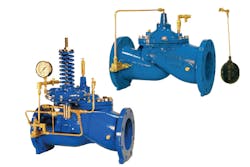
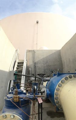
Water is an essential resource to everyday life, and having a way to store and distribute water is important. Water storage tanks have been designed to compensate for varying water demands during high- and low-peak periods, as well as for firefighting, power outages and other emergency demands. Water can be stored in many ways in a distribution system, but the control system must ensure that water storage is accomplished correctly. Common practice is to use different hydraulic altitude water control valves. A control valve uses hydraulic control pilots, depending on the application, to measure the tank levels and maintain or adjust the water storage levels. The two key factors for water storage are to ensure that the tank maintains the correct level and that water turnover occurs.
Turnover
Water quality deteriorates with water age, so stagnant water in tanks severely reduces the quality of the water. Water quality deterioration can give rise to different health risks. Poor water storage can have both chemical and biological impacts – such as, disinfectant decay, microbial growth, tank corrosion, chemical contaminants, nitrification, pathogen contamination and sediment build up.
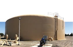
Water storage tank controlled by a control valve in Modesto, California
Another issue, less common but still a factor, occurs in colder climates in which low tank turnover can lead to the water freezing within the tank. Water in motion during tank turnover is far less likely to freeze. Freezing can cause an altitude water control valve to lose the ability to sense a full tank and, therefore, can cause the storage tank to overflow.
Freezing also can cause internal and external structural concerns. The ice expansion may put pressure on rivets or on bolted or welded seams. Additionally, freezing may lead to pipe breaks and cause leaks if corrosion previously formed when ice pressure was produced.
In an ideal situation, the altitude water control valve controls the tank water level to the set maximum of a hydraulic control pilot. Following this, the altitude water control valve closes, and then the distribution line is opened. This allows the tank to drain down to a satisfactory level so that enough water turnover can be accomplished before the altitude water control valve opens again to fill the tank to the set maximum.
In a two-way altitude water control valve situation, the same is true except the distribution is through the same valve as the filling cycle. In this case, the altitude water control valve still will close when the maximum of hydraulic control pilot is met but then will re-open when the differential pressure in the line is reversed, allowing the water to distribute in the opposite direction.
Ideal operation is not always easily achievable because system characteristics can change continuously and affect the system. As system demand changes, so does the pressures in the system. Commonly, incoming pressure to an altitude water control valve drops off, or the demand on the distribution system pressure/flow demands change.
Altitude water control valves operate off differential pressure of the inlet of the valve to the tank-level head pressure. Consideration needs to be taken to ensure the inlet pressure of the altitude water control valve is always greater than the tank-level head pressure. If the system fails to have a greater inlet pressure, the system essentially equalizes the inlet pressure of the altitude water control valve and tank-level head pressure. With zero differential pressure, the altitude water control valve will essentially sit, floating open, trying to fill the tank but never reaching the maximum level setpoint. With zero differential pressure, the system essentially sits at a static flow and pressure, and therefore, no water will flow in or out of the tank, which means there will be no tank turnover.
To fix this situation, the set maximum of the hydraulic control pilot needs to be adjusted and set to the correct tank level, or the system inlet pressure needs to be increased above the desired tank-level maximum setpoint. Adjusting the hydraulic control pilot entails a site visit to adjust the set screw of the altitude water control valve, which can be quite cumbersome in remote sites when many changes are needed to facilitate system changes. Increasing system inlet pressure entails either ramping up pumps in the system or adjusting the feeder zone pressures higher. Both situations add time and cost but can also increase water loss and add strain on the system due to extra pressure, which could result in additional pipe breakages.
Automation & solenoid control
Automation and instrumentation is a growing market in the water industry – and for good reason since many systems are moving toward full, remote autonomy and control. Hydraulic altitude water control valves have controlled tank levels for many years, but now the same control can be accomplished with control panels and instrumentation.
By replacing traditional hydraulic control pilots used to sense level with electronic tank-level/pressure switches or sensors paired with a control panel, the level control process can be achieved electronically. The hydraulic water control valve still remains. However, a complex hydraulic pilot system, as described in the previous section, is not required. All that is needed is a simple, single solenoid.
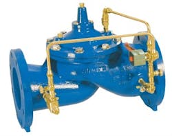
Solenoid-operated control valve
Level & pressure switches
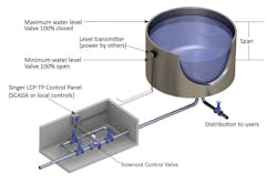
Once automation control is installed, one of two operational sequences can be used for the level control. The first sequence entails using one level/pressure switch located at the maximum-level setpoint and a second one at the tank-drawdown setpoint. If the water level is located below the tank-drawdown switch, then the panel will open the control valve via the solenoid and allow the tank to fill until the maximum-level switch is contacted. The panel will then close the control valve using the solenoid.
The control valve will remain closed until the tank level is once again drawn below the drawdown switch. Although this is an effective technique and provides more flexibility than the basic hydraulic altitude water control valve, the maximum level and drawdown switches still sit at a constant level. They would need to be adjusted accordingly on site to allow for variations of the setpoint, which must sometimes be adjusted to accommodate changes in system pressures.
Level & pressure transmitters
A more versatile option, which is the second operation sequence, is to use a level/pressure transmitter. These are available in all shapes and forms to fit specific tanks. These level/pressure transmitters offer a 4-20-milliampere (mA) feedback signal to the control panel that gives the panel the exact tank level. With a live feedback signal, the panel provides many more options for determining the tank-level setpoints. The level control panel can then calculate a variable setpoint for both the maximum level and drawdown, which easily can be changed with the user interface on the panel. This eliminates the need for a site visit to change any setpoints and allows the system setpoints to be changed as needed to ensure optimum operations.
New level control panel
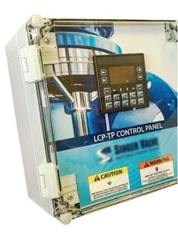
The Level Control Panel with Touch Panel interface designed by Singer Valve was created to accomplish optimum level control feasibility and flexibility. This level controller was designed to complement a single solenoid-operated/override control valve and 4-20-mA level sensor or high/low level switches. This combination package is ideal for filling and controlling any water tank that requires a filled, level setpoint and a draw-down-level setpoint before activating the fill cycle again to ensure tank turnover.
Level control panel
This system is easy to configure, read and compare the level 4-20-mA signal to the desired setpoint. The setpoints can be set locally with an interactive button display screen or remotely with either supervisory control and a data acquisition Modbus or hardwired 4-20-mA, remote-setpoint signals. If a high- or low-level switch system is preferred, this panel can switch the configuration to allow for level switch inputs and regulate the control valve accordingly. Data logging is also a useful feature to log sensor feedback and setpoint data with a time stamp, allowing for system analysis.
The biggest benefits of this automated level controller are the flexibility and readability of the control. For the user who wants to set up a full communication network that can access all the storage tanks and control them remotely, this is easy to accomplish with Modbus and remote 4-20-mA communication options. For the user who has a remote site but wants to log data and analyze tank turnover, the system offers a data logging feature. Either option offers feedback and traceability of the system’s operation. Based on this information, the tank level setpoints can be adjusted to match the needs and demands of the system with simple interaction to ensure that the system can function optimally. This ability to take all the information and then easily adjust the tank setpoints is a benefit.
Although the system does not eliminate tank turnover issues because it still needs to be operated correctly, having access to all the feedback information should allow insight into setting the system to operate to ensure proper water turnover. For example, the live, level feedback lets the system know when it is sitting statically, which allows the user to easily rectify the issue and regain control of the system and prevent the water from sitting stationary in any tanks.
A remaining feature that fits into the readability of the system is alarm/notification output. Instantly knowing if something goes wrong with the system allows procedures to be implemented right away in order to rectify the problem. Not having access to these alarms could mean the system is assumed to be operating correctly until closer inspection occurs, or worse yet, until something goes drastically wrong – such as tanks overflowing, pipes breaking, the system being over pressurized or the development of stagnant water contamination, a common theme.
Electronic automation of level control means that gone are the days of relying on remotely located hydraulic pilots with no way of telling what the system is doing. The level control process now sits at an end user’s fingertips, delivering accurate and safer water storage.
Tank application example
Ryan Spooner is an engineer and head of Automation and Instrumentation for Singer Valve. He has a degree in mechatronics engineering from Simon Fraser University and a deep understanding of electronics with a solid background in valve mechanics. Spooner designs and builds customized control panels and does commissioning and valve integration. He also runs operator training sessions on-site as well as lab demos at the manufacturing plant.
Singer Valve – http://www.singervalve.com
